Assembly
Steps:
- Materials
- Disassemble the Camera Module
- Join the Camera Module and the Electronics
- Preflight Test and Focussing
- Finish the Enclosure
- Take images
- Copy the Data
- Postprocessing
One word of caution though: This is a very low volume DIY kit of 3D-printed parts, not industrial-grade perfect consumer goods. However, I did my best to make assembly as easy and reliable as possible, if you encounter issues, have a look at the troubleshooting guide or let me know and I help you out.
Materials
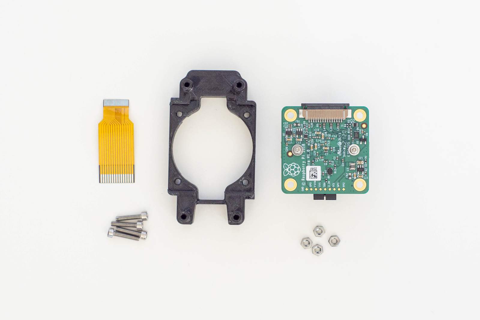
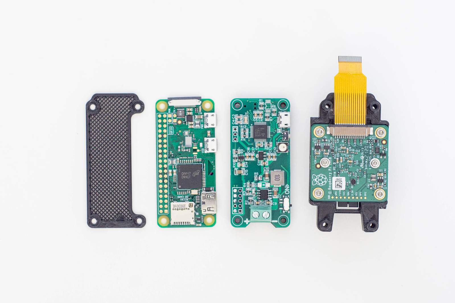
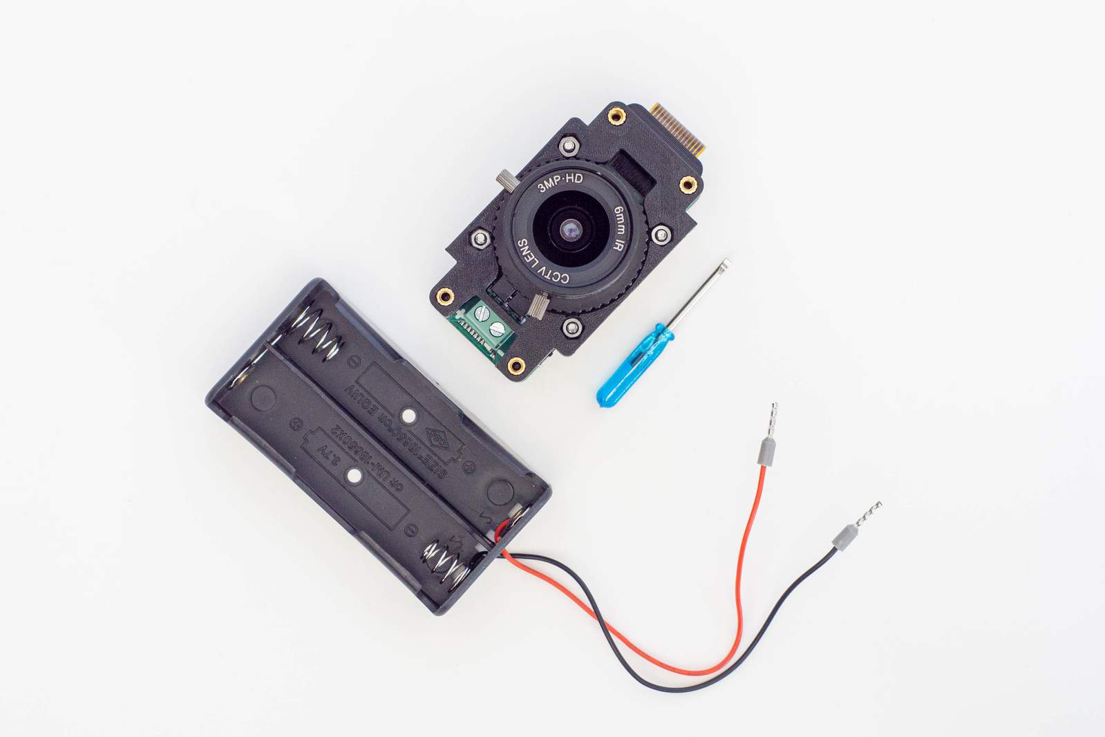
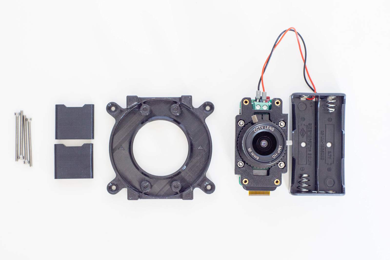
Make sure you’ve got all necessary parts:
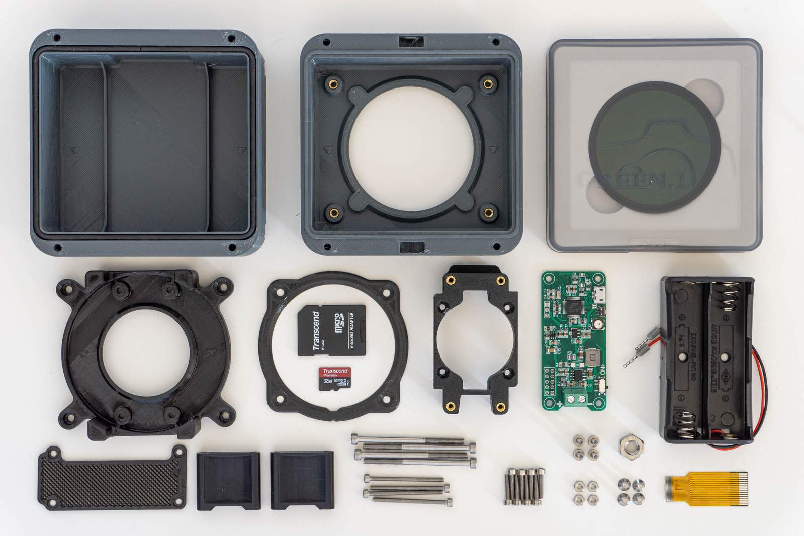
Part of the kit:
- the CompressorCamera-board to control your pi
- ND64 neutral density filter
- 3d-printed enclosure
- Raspberry Pi Zero camera cable
- 18650 battery holder for 2 batteries
- Micro-SD card (pre-loaded with the software)
- all required fasteners and spares
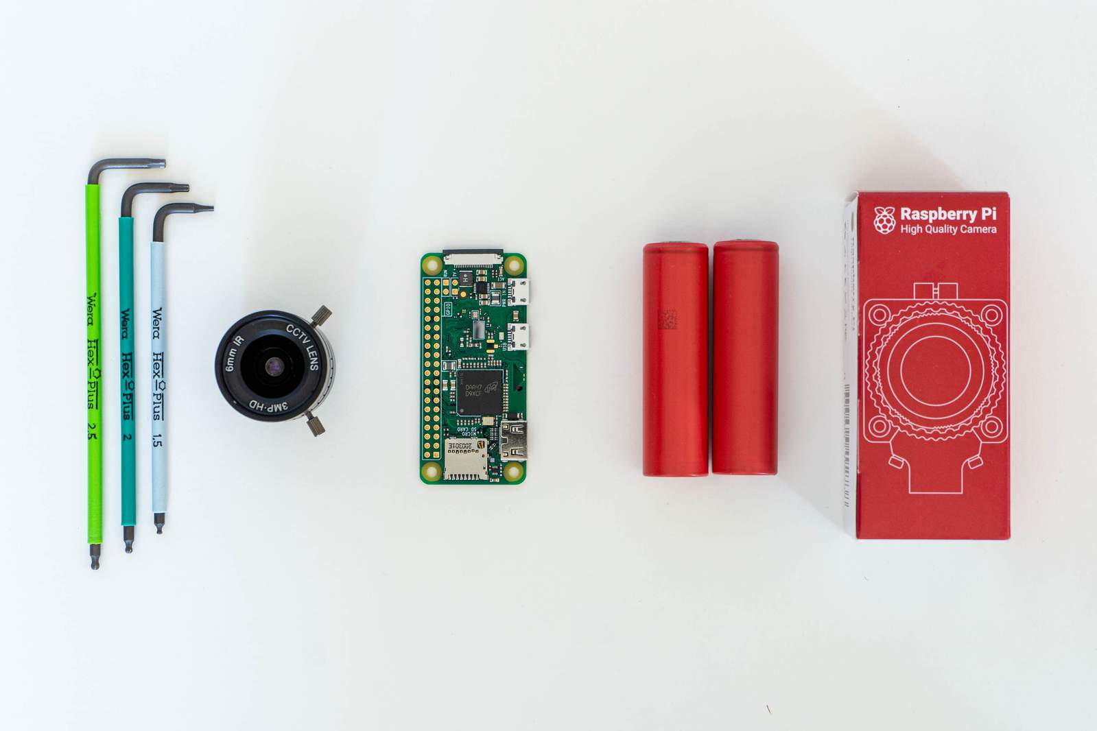
Whats you need to buy separately:
- Raspberry Pi Zero W (without headers)
- Raspberry Pi Zero HQ camera module
- C or CS-Mount Lens (see lens size for more info)
- two 18650 Lithium-Ion batteries (and a charger)
- metric Allen-keys (sizes: 1.5/2/2.5mm)
- a tripod or zip ties
See the buyers guide for recommendations.
Please make sure that everything is present and looks fine. Some plastic parts in your box may differ slightly from what is shown in the images, from time to time I am improving things a bit.
Disassemble the Camera Module
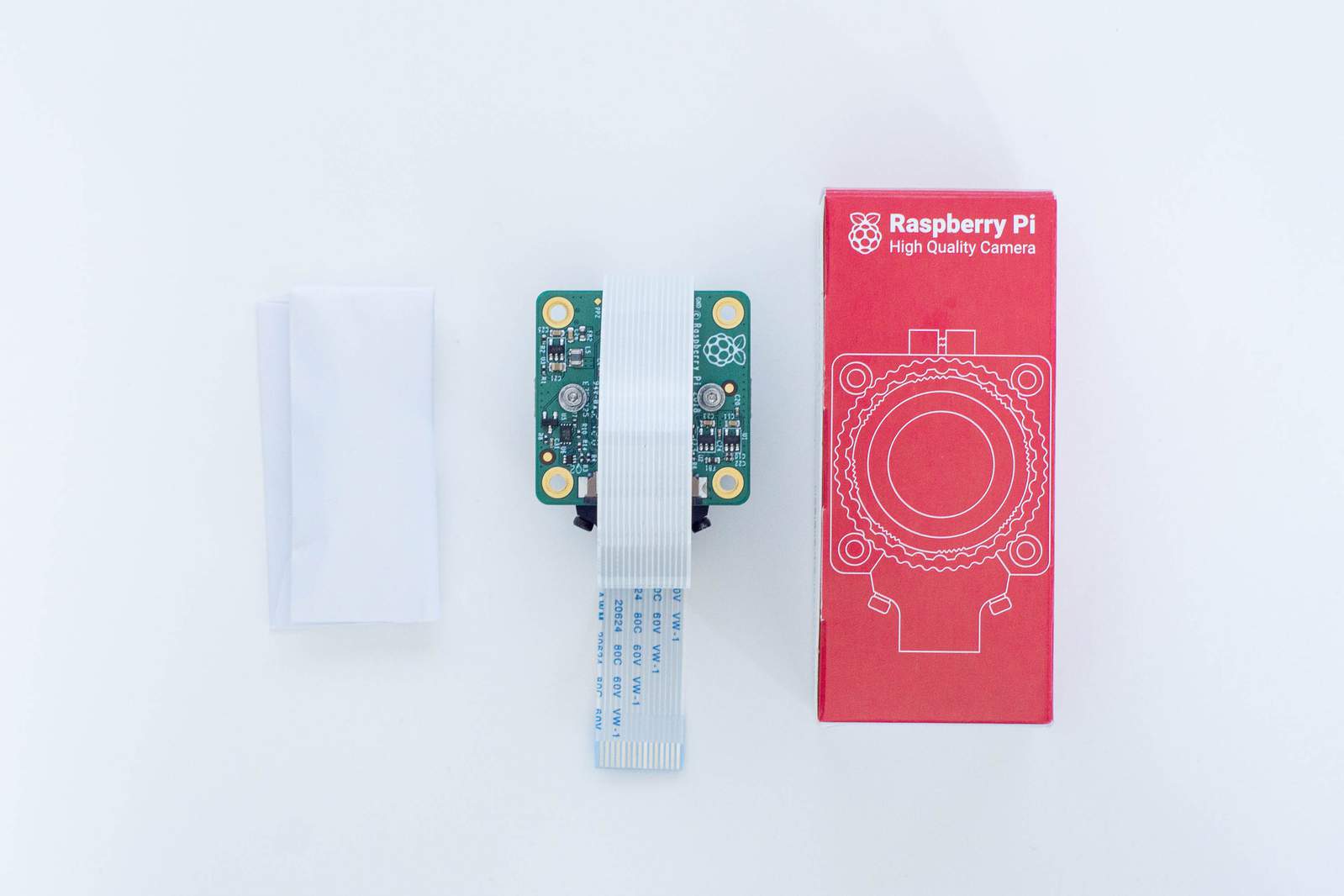
Let’s start with the assembly by preparing the camera module. Get the camera module and open the packaging. Sometimes there may be a flat white cable attached to the camera, sometimes the cable can be found in the packaging. The white cable does not fit the Raspberry Pi Zero so we need to remove it in case it is attached. Additionally you will find a tiny flat-head screwdriver in a paper pouch. Keep the screwdriver, you’ll need it to tighten a screw after focussing.
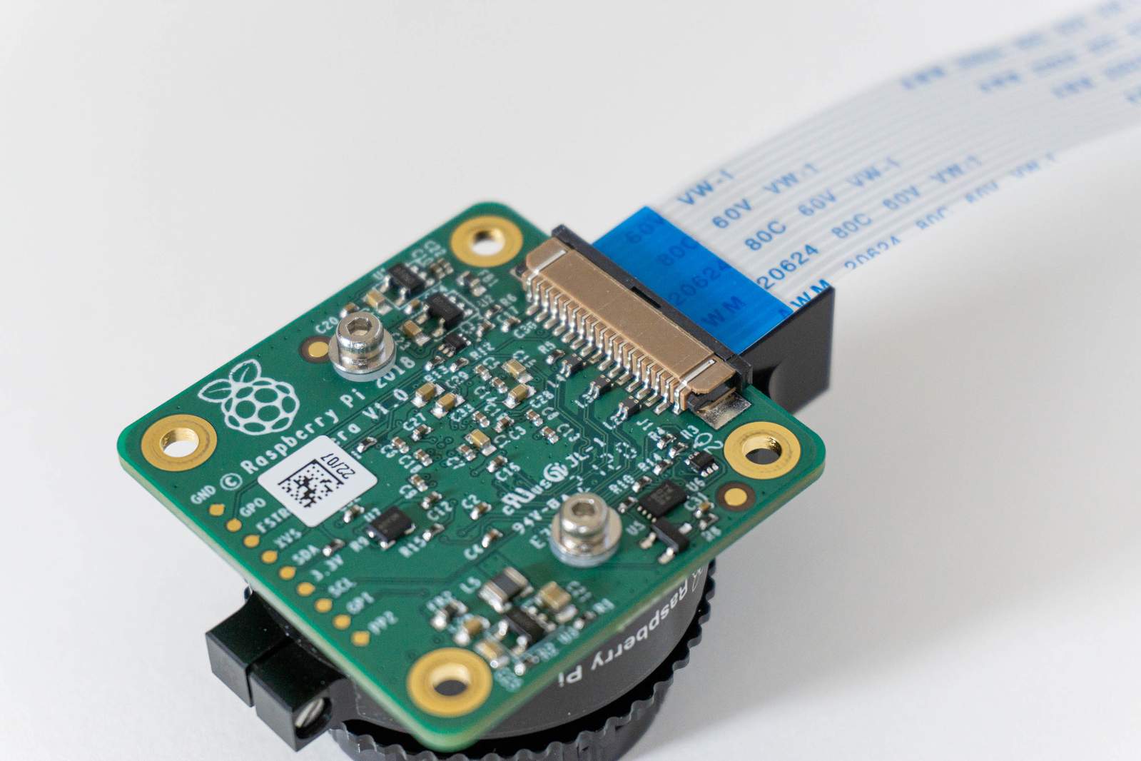
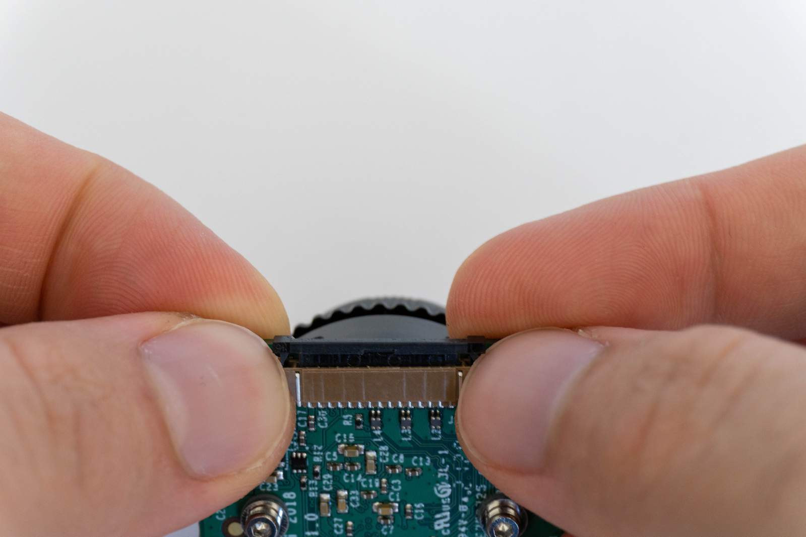
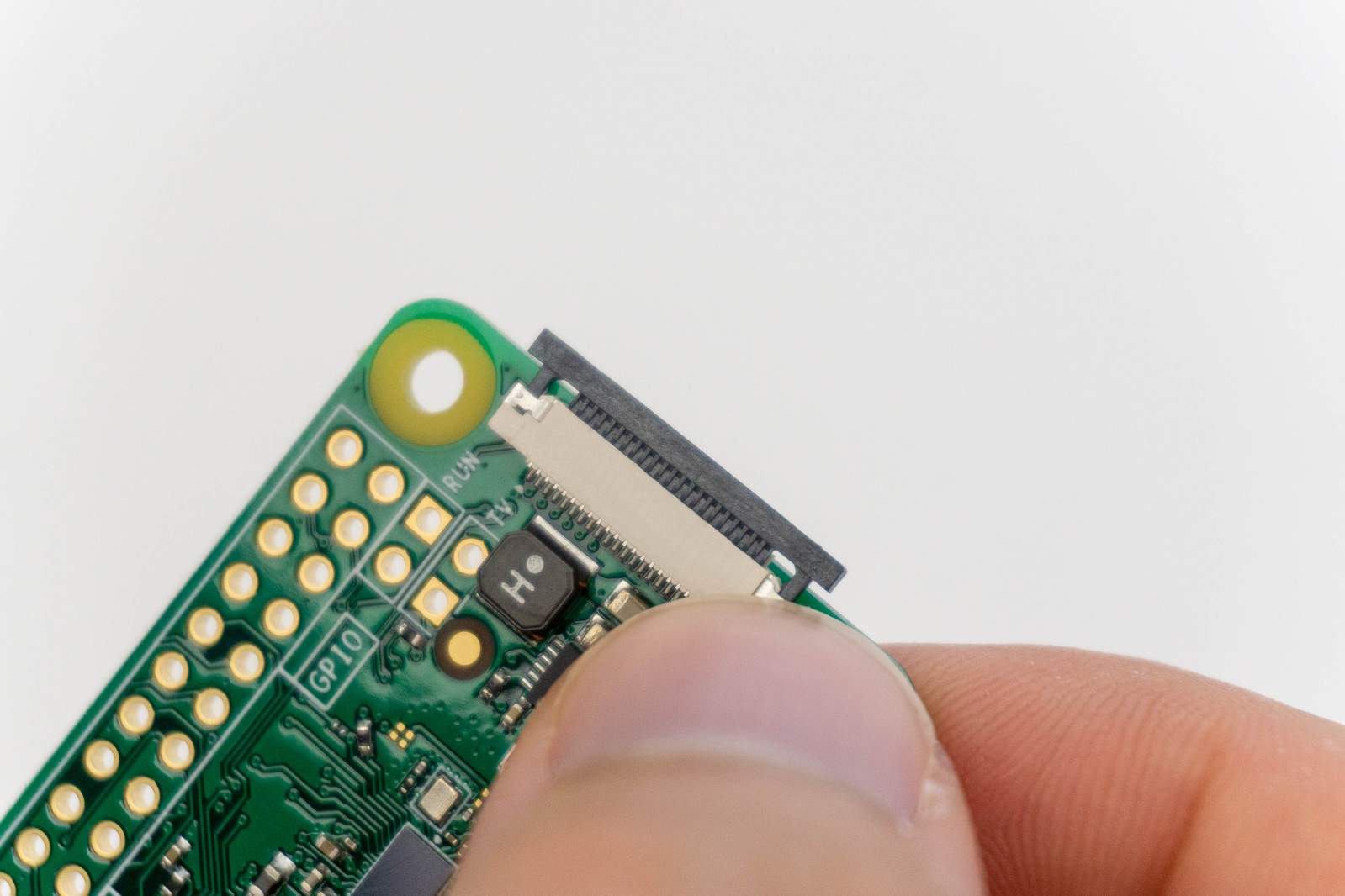
A word of caution beforehand: be careful, excessive force may break the connector.
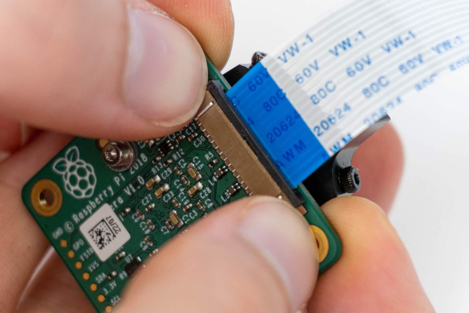
Put your fingernails on the tiny plastic nudges of the connector and push the plastic bar gently towards the cable. You will be able to move it about a millimeter.
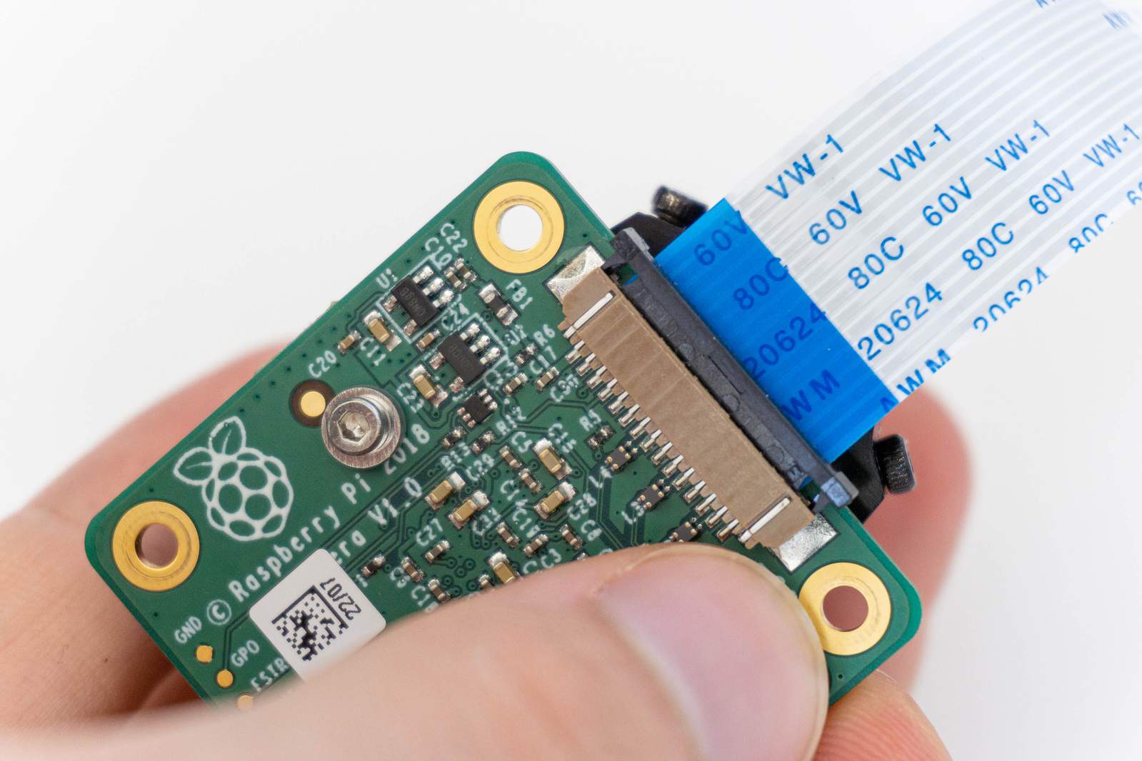
Afterwards the cable is not secured anymore and can be pulled straight from the connector.
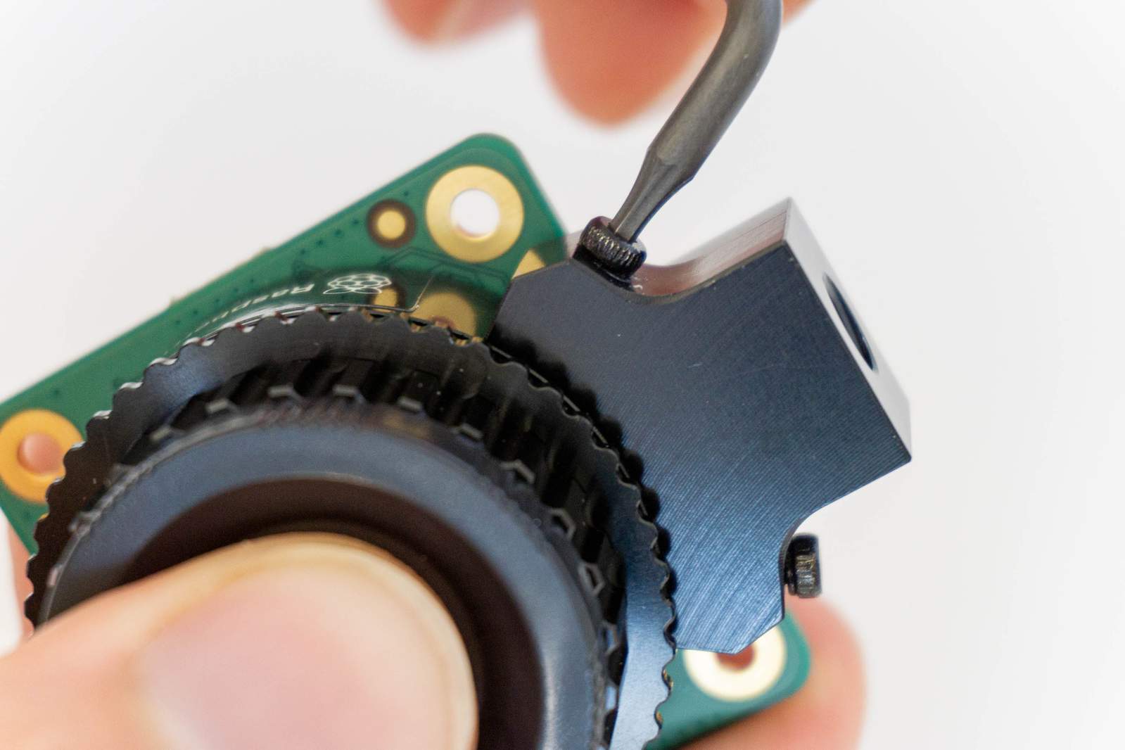
Second step: remove the tripod mount. For this you will need an Allen key of size 1.5mm. Unscrew both screws on the left and right side and remove the metal part with the threaded hole. Keep the screws and the mount in case you want to use the camera module in a different way in the future.
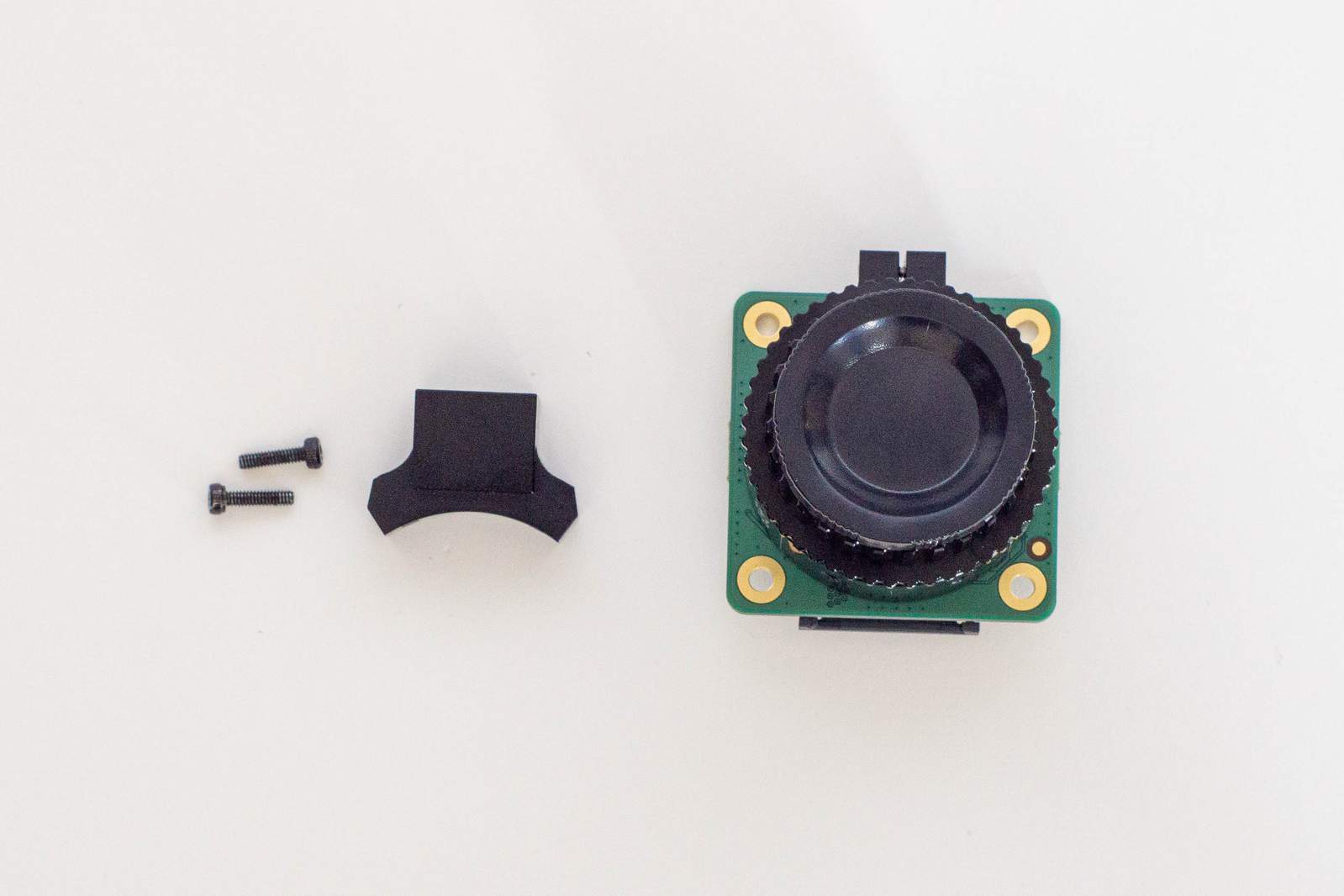
The Camera Module is fully disassembled now.
Now we need to put it back together with the correct plastic parts.
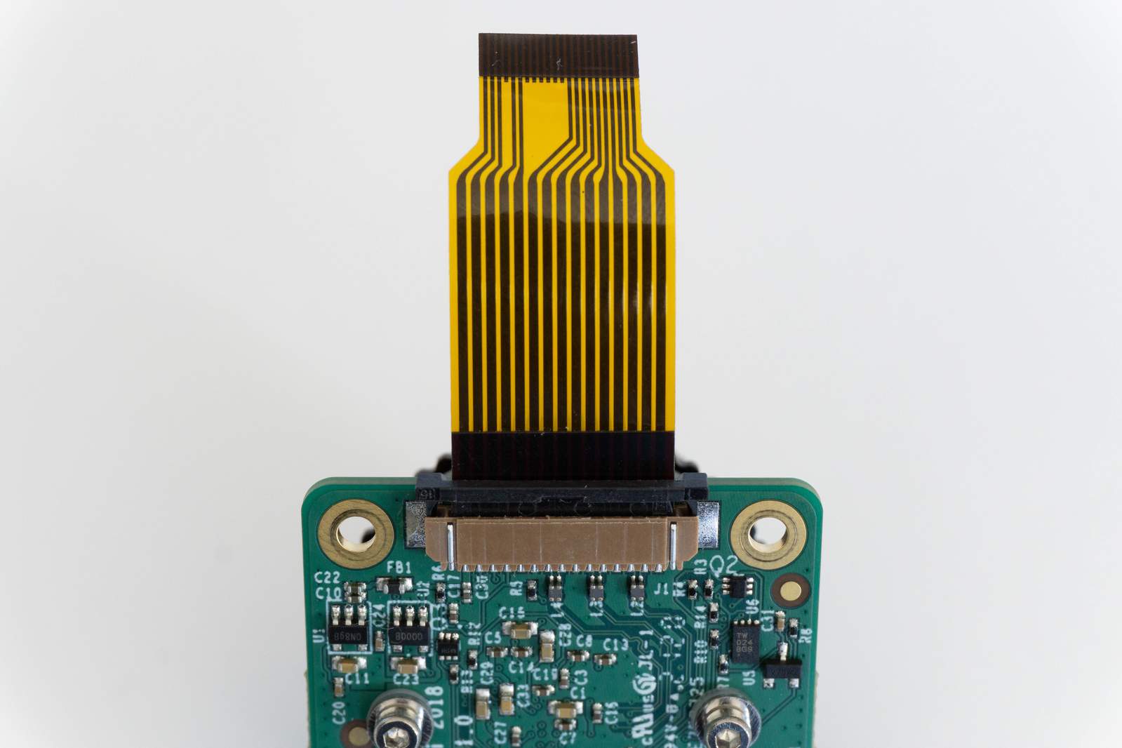
First step: grab the orange camera cable and align it as shown in the photo. Wide end facing the camera, exposed metal side facing towards the circuit board. Push the cable straight into the connector (about 2mm deep) and hold it with two fingers while you secure the connector again by pushing down the plastic bar. The camera module now needs to be screwed to the corresponding 3D-printed plastic part.
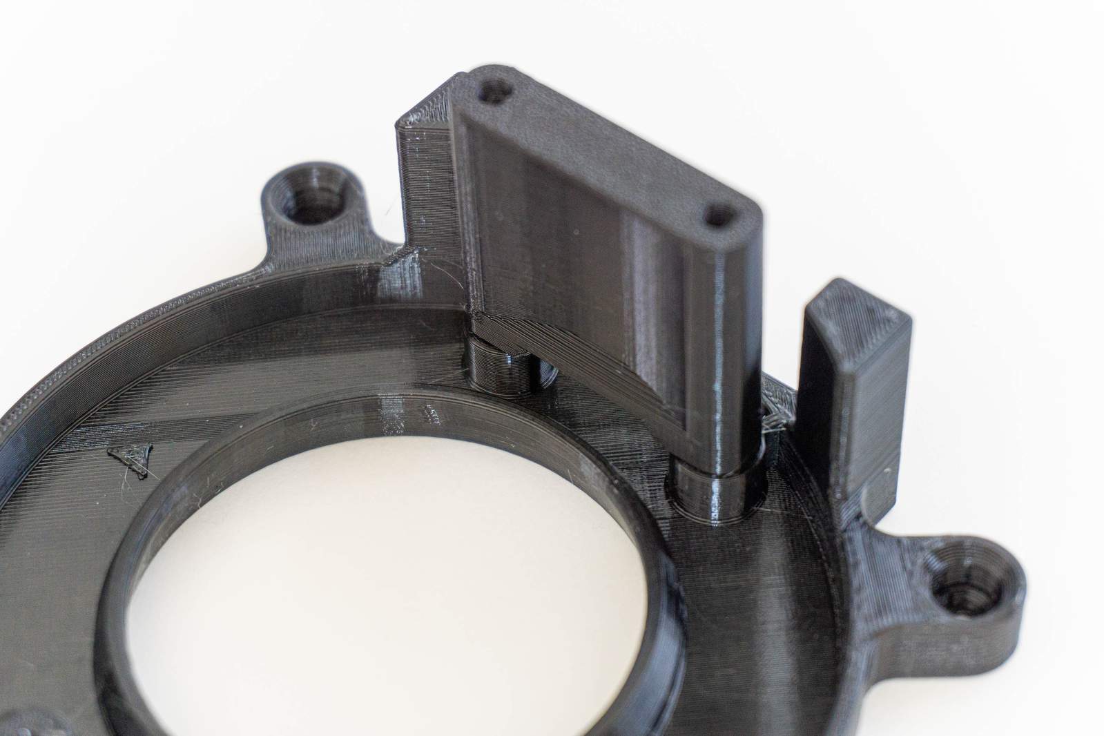
We will now attach the Camera Module to main plastic part that holds everything. While you are able to fit the module in two ways in the plastic part, we need to orient it as shown in the picture below (but don’t push it in just yet).
A word of caution again: the plastic part is manufactured with a 3D-printer. Excessive force while tightening the screws will break the plastic. Always use enough torque so that the screw sits nicely, but never use more force than you would be able to apply with two fingers on the screwdriver.
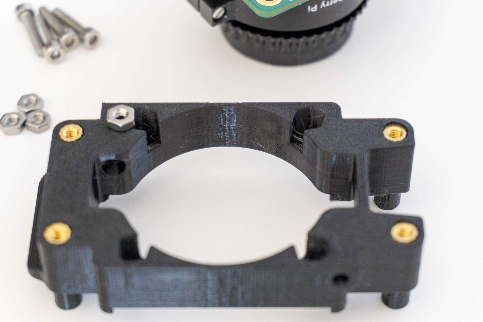
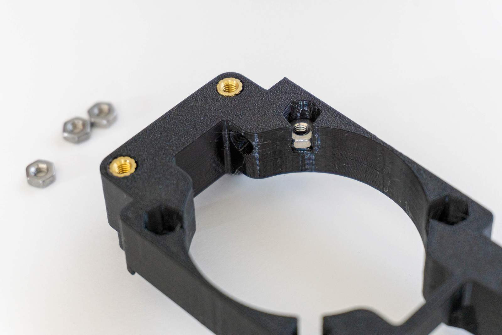
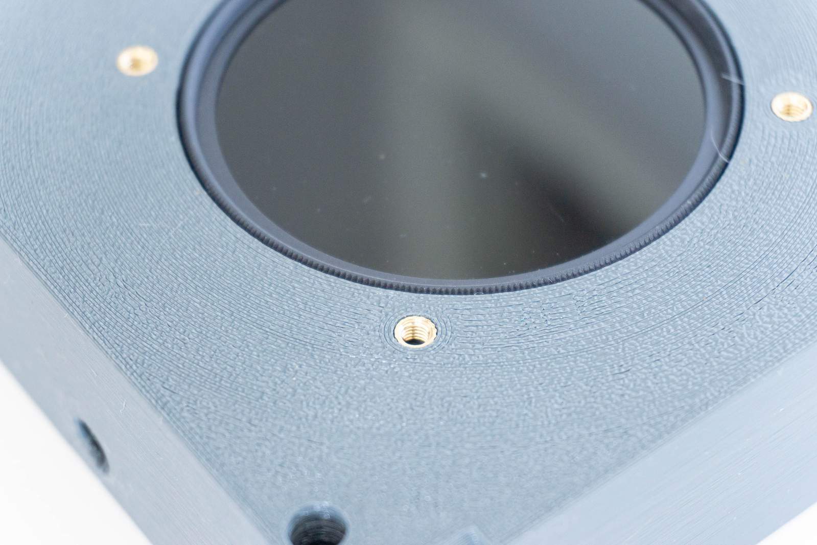
Put a nut in each of the four holes shown in the photo. Often using the screwdriver makes it easier to push the nut in the hole (the nut doesn’t need to touch the bottom of the hole, this happens during fastening).
Push the metal ring of the camera module through the plastic (take care, that might be a tight fit) and screw it down using four 12mm long screws. (2mm Allen key needed).
Double check if you did insert the camera module in the right orientation (cable should be facing away from the cavity as shown in the picture above).
That’s it, first part is done.
Join the Camera Module and the Electronics
For the next part we need the Camera Module in it’s plastic part, the CompressorCamera board and the Raspberry Pi Zero W.
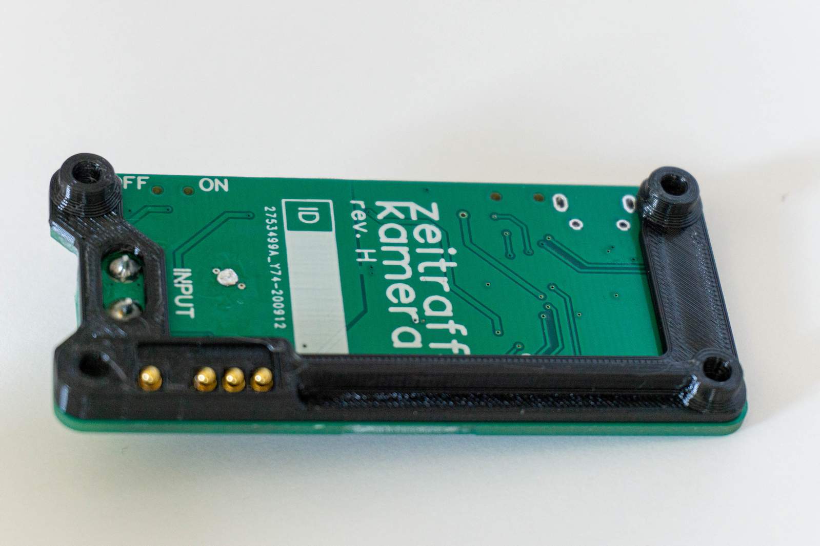
The CompressorCamera board should come with a plastic part attached to the golden spring-loaded pins. If that’s not the case, find the part in the box and place it again on the board as shown in the image.
Since it will be hard to access the camera cable connector on the Pi Zero later on, we need to connect the camera cable now.
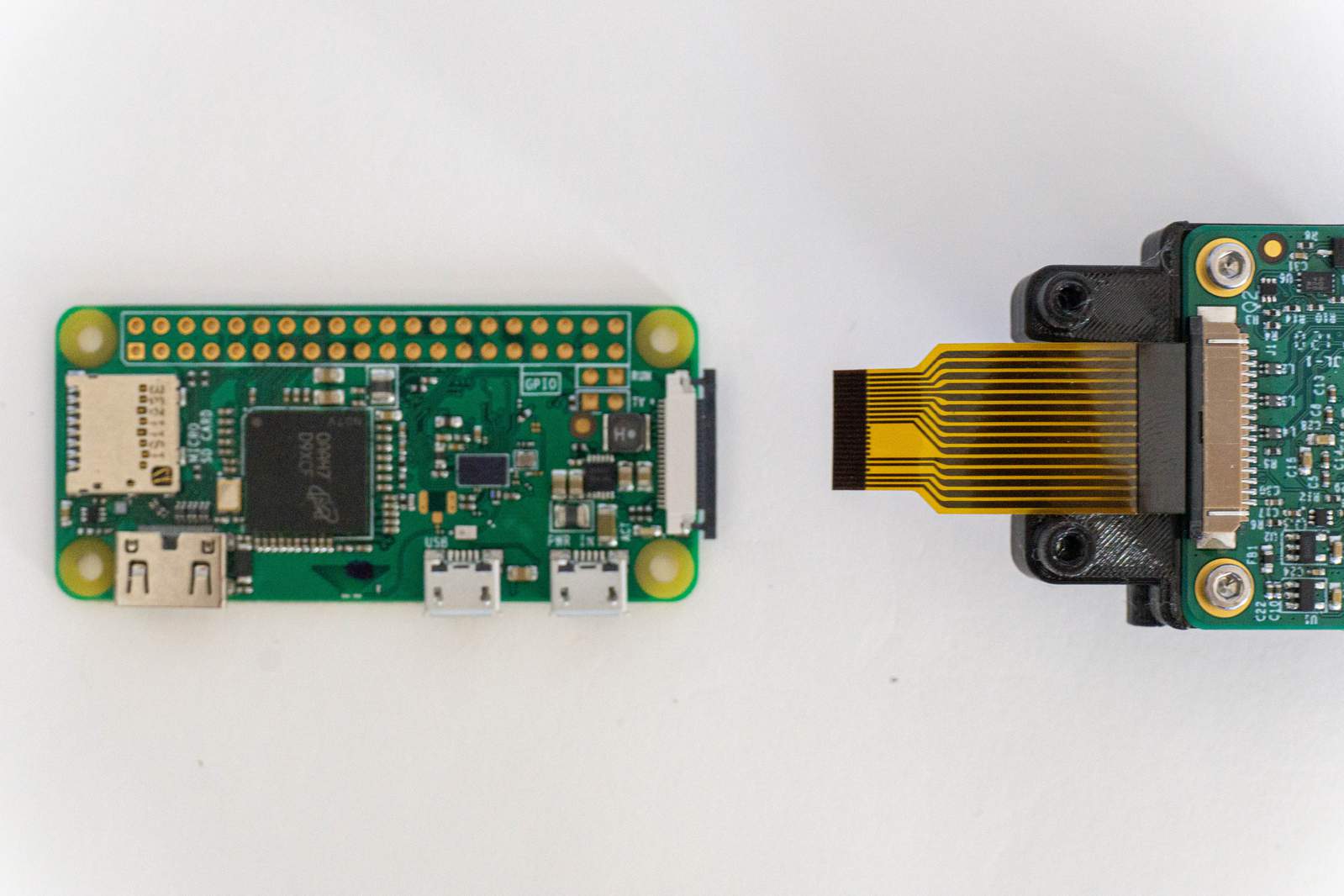
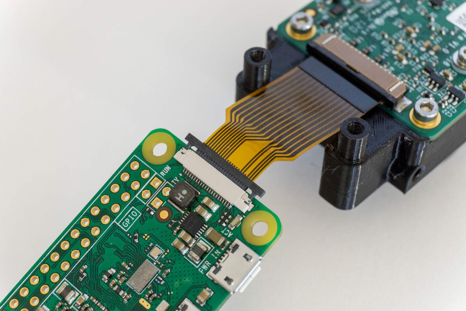
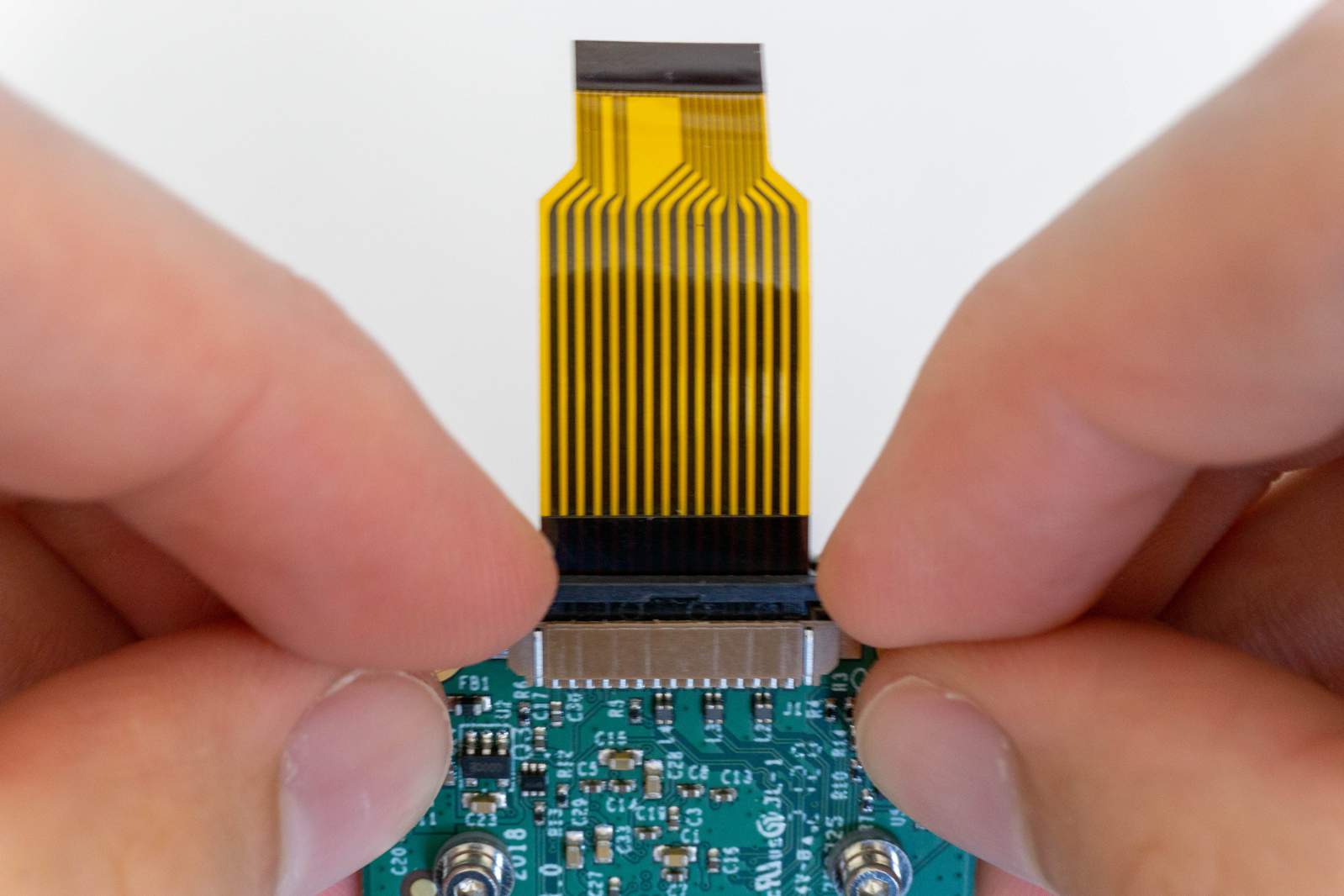
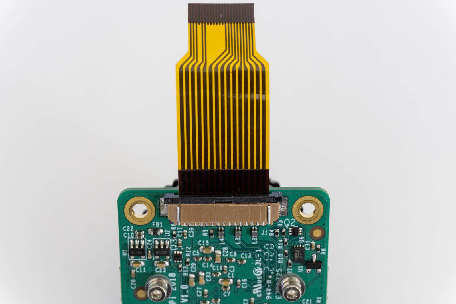
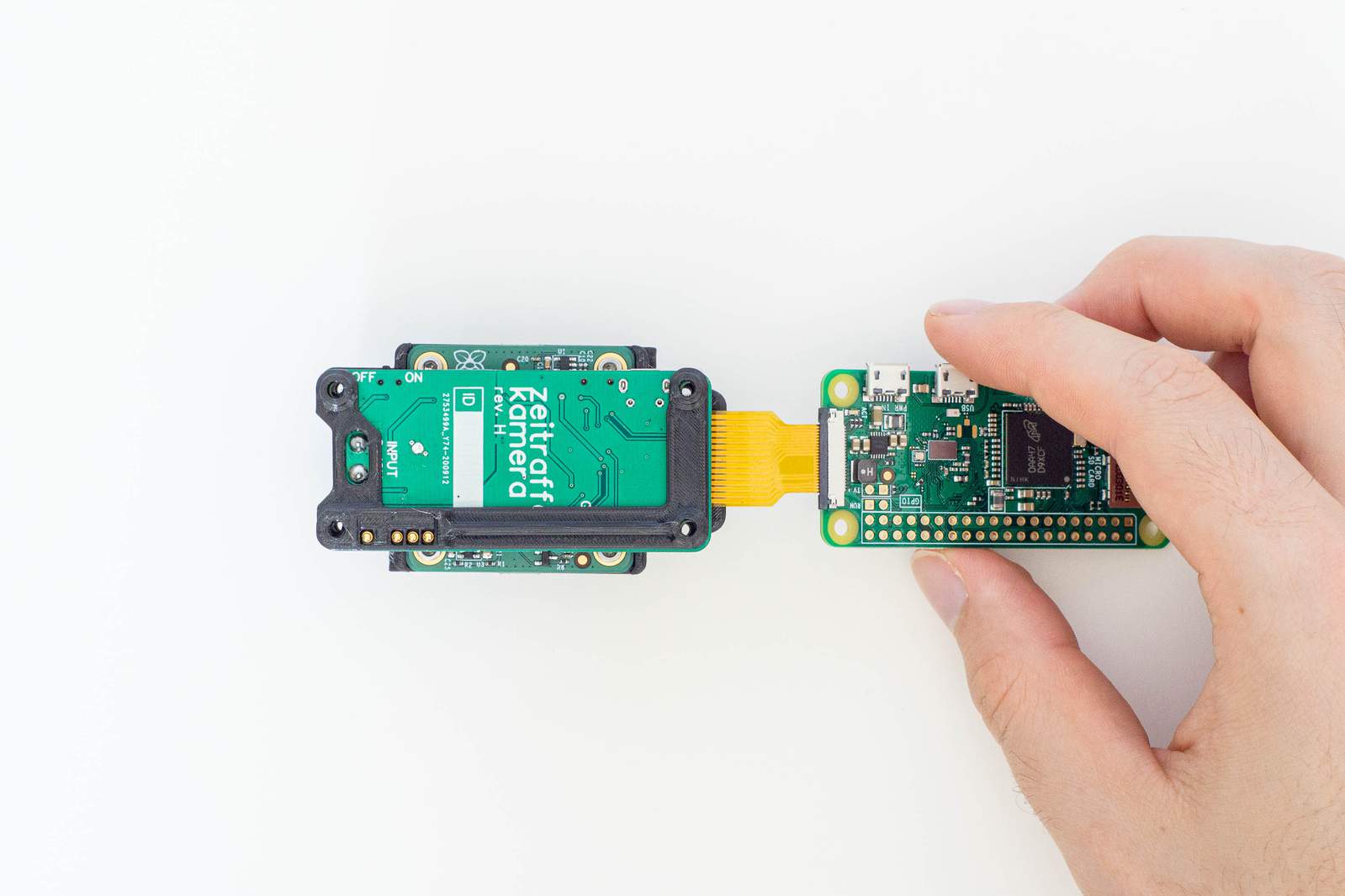
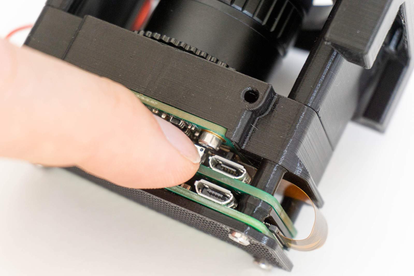
Same procedure as the Camera Module, use your fingernails to open the connector. Be extra careful now, this connector is even more sensitive than the one of the Camera Module. Orient the cable of the Camera Module in a way that the exposed metal part of the cable is facing down towards the Pi Zero board (as shown in the image). Slide the cable into the connector and then gently pull it back to secure it again.
The smaller half of the cable may show exposed metal on both sides. If this is the case double-check if you are doing it in the right way by comparing the direction of your camera module and your Pi Zero board to the image. They need to face in opposite directions.
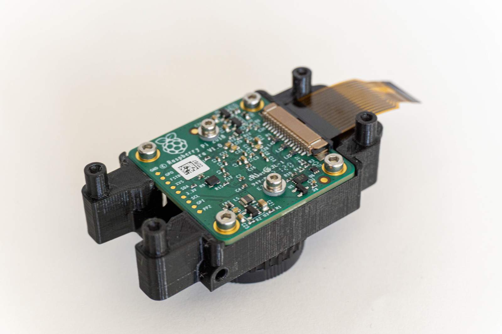
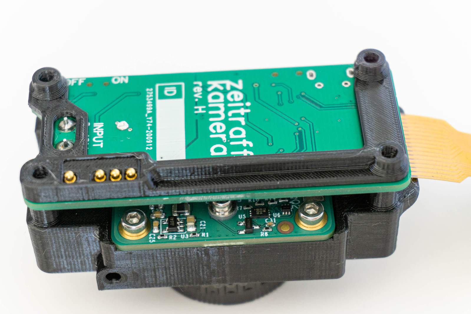
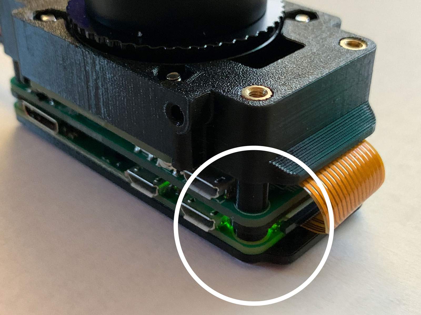
Now place the CompressorCamera board on top of the Camera Module (orientation as shown in the image). Depending on your hardware version, the white markings on the bottom of the circuit board may look different.
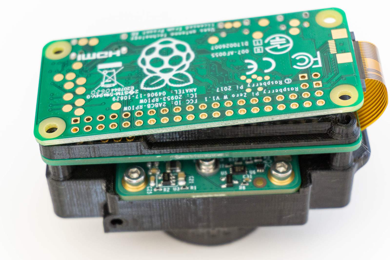
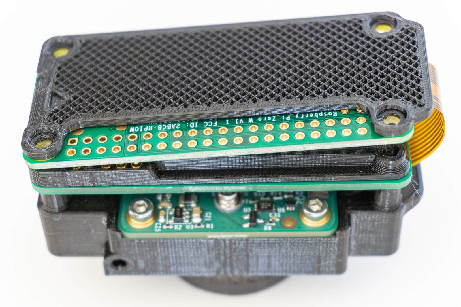
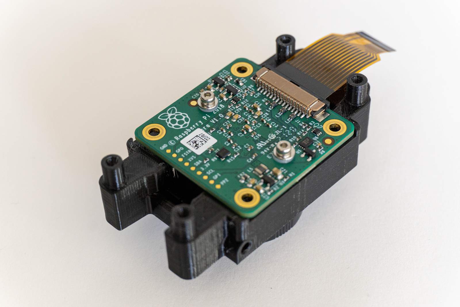
Flip the Pi Zero gently over the camera board, place the bottom plastic part on top of the Pi Zero and double check that the orientation is correct (wedge towards camera connector). Use four 12mm screws to screw everything together.
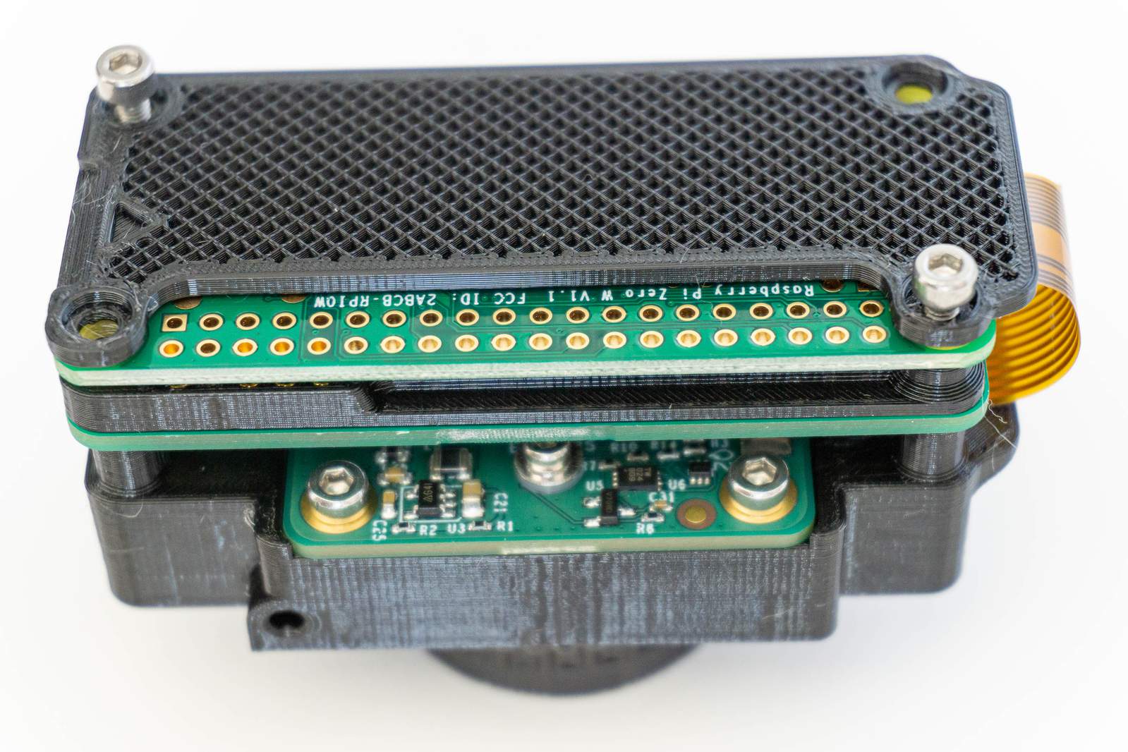
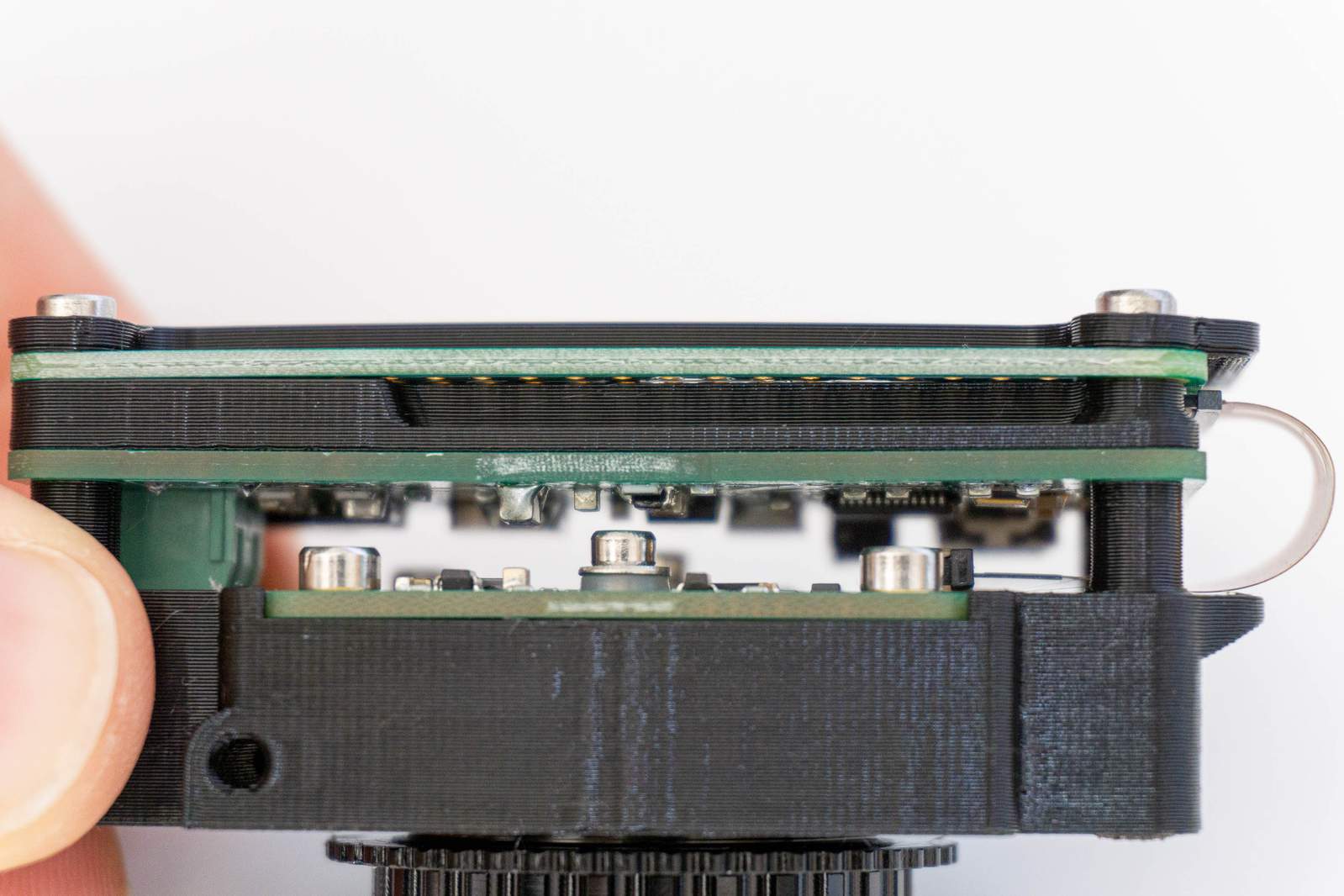
These four screws will directly screw into the plastic part so there will be slightly higher resistance. Again, do tighten them but do not overtighten them. The screws are responsible for applying the pressure on the spring-loaded pins that connect CompressorCamera board and Pi Zero without the need to solder. If they are overtightened they may deform or crack the plastic. If they are undertightened, the connection between the boards is unreliable and the camera may have unexpected hiccups.
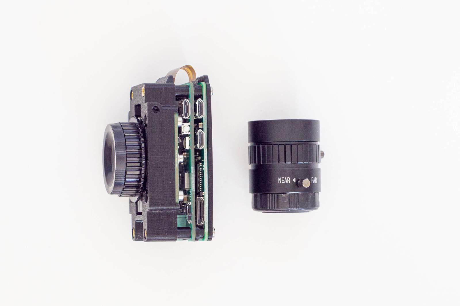
Finally: attach the lens. Grab your lens and remove the rear cap from the lens and the front cap from the camera module. If you have a CS-mount lens such as the official 6mm wide-angle, the adapter ring needs to be removed. Screw the lens in and you’re done (for now).
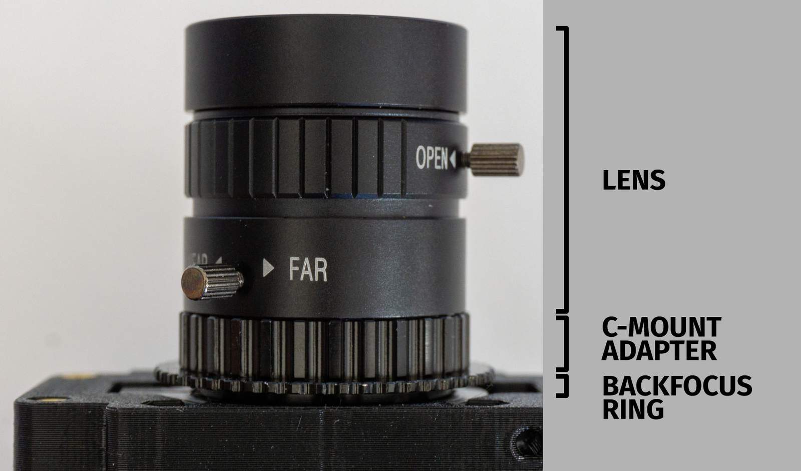
Do not remove the backfocus ring. If you are using a C-Mount lens, do not remove the C-Mount adapter ring. If you are using a CS-lens such as the Raspberry Pi’s official 6mm wide-angle lens, remove the C-Mount adapter ring then screw the lens into the backfocus ring.
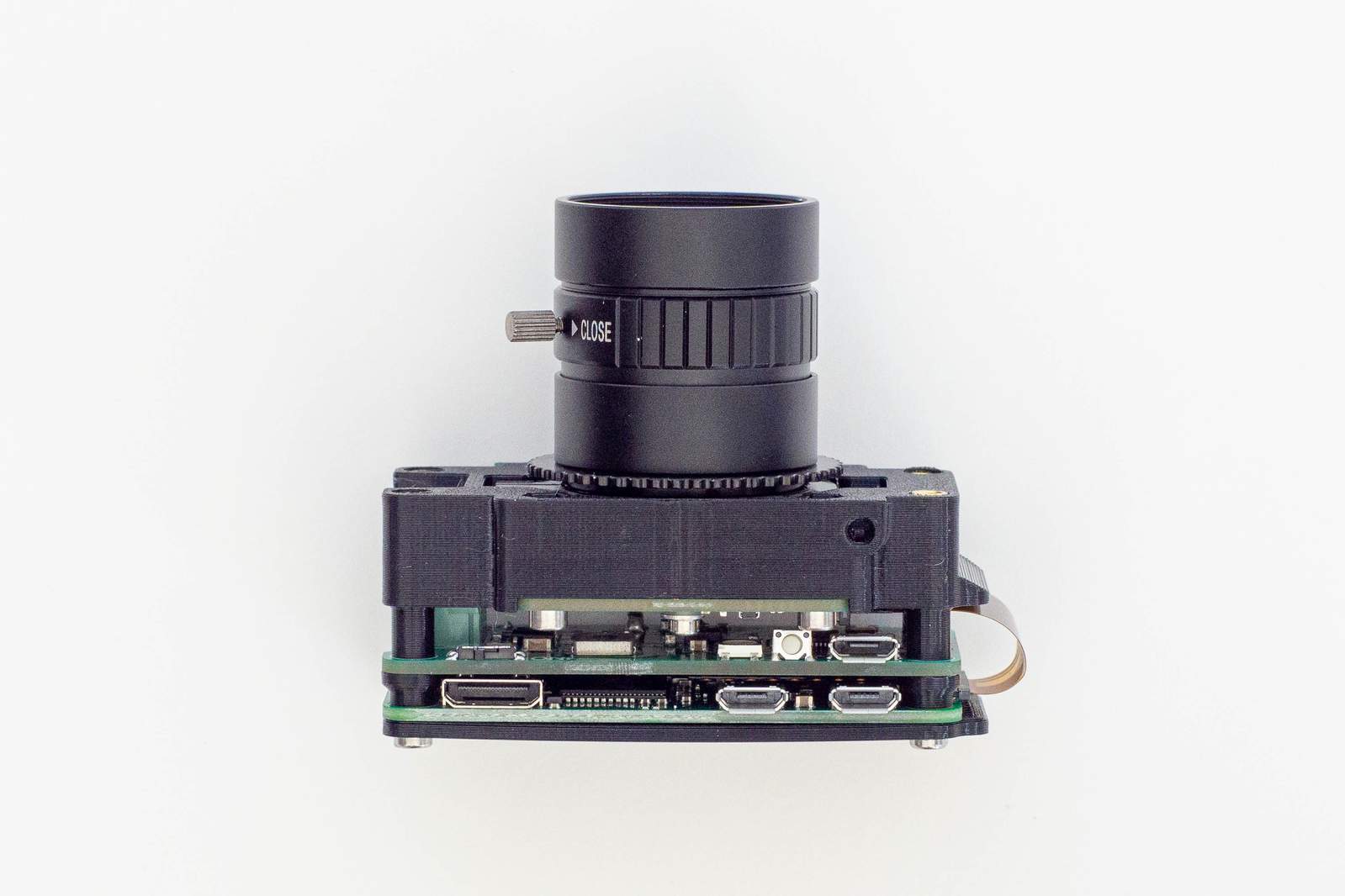
(If you’ve got a CS-lens, it should look like this)
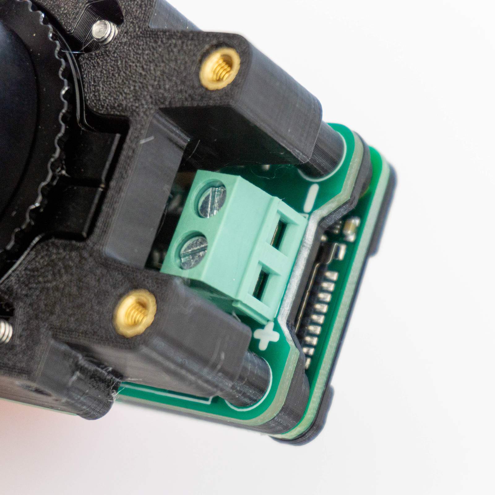
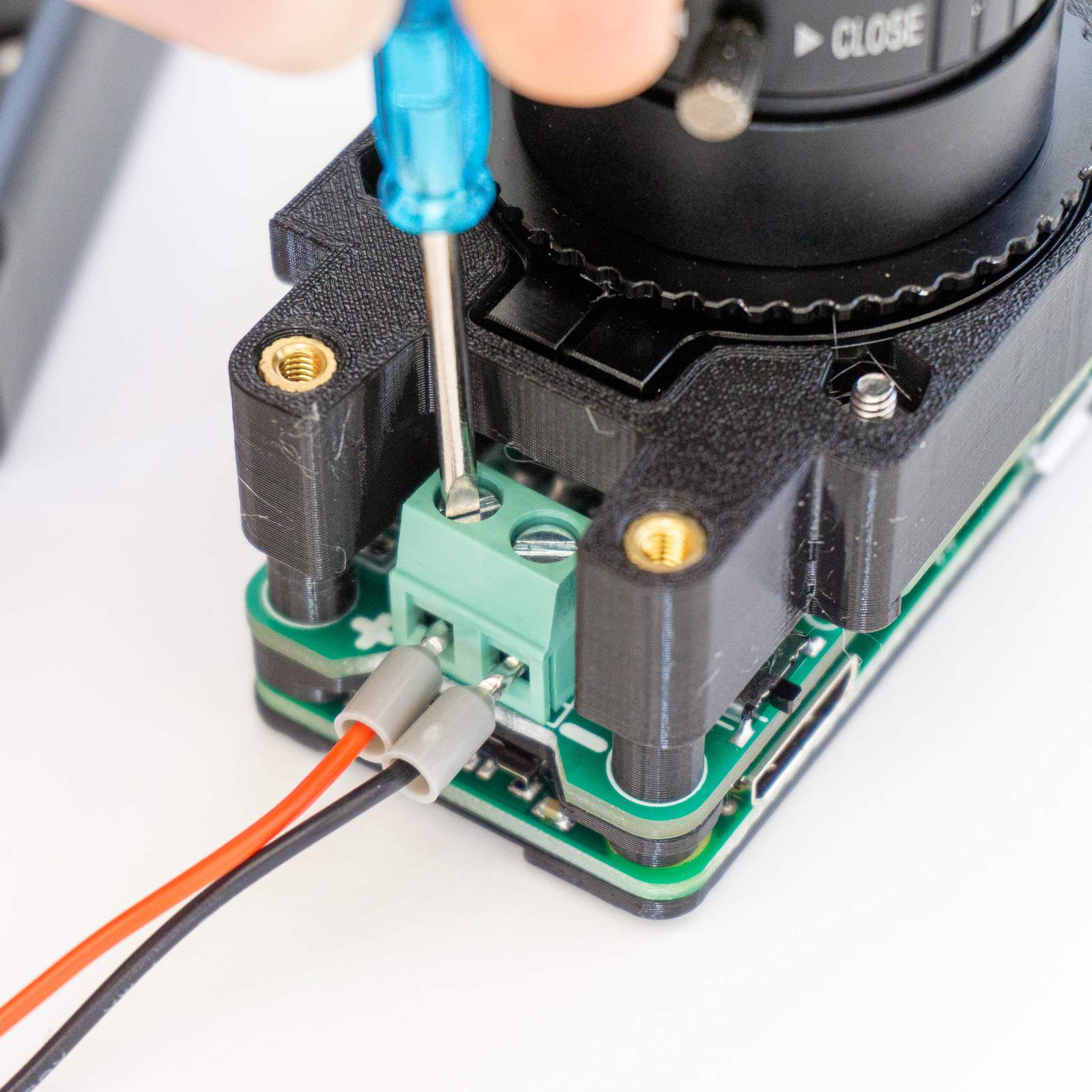
Last step: plug in the battery holder. The CompressorCamera board comes with a screw terminal to fix arbitrary battery holders or power sources to the board. Use the blue screwdriver that came with the Camera Module to loosen the screw of the screw terminal and push in the leads of the battery holder gently. Make absolutely sure that you do not swap the polarity. Red must be connected to plus (+), Black to minus (-). Tighten the screws of the screw terminal again and check if everything is secured. It’s okay to tighten these two screws a bit more than those connecting to 3d-printed parts.
Preflight test and focussing
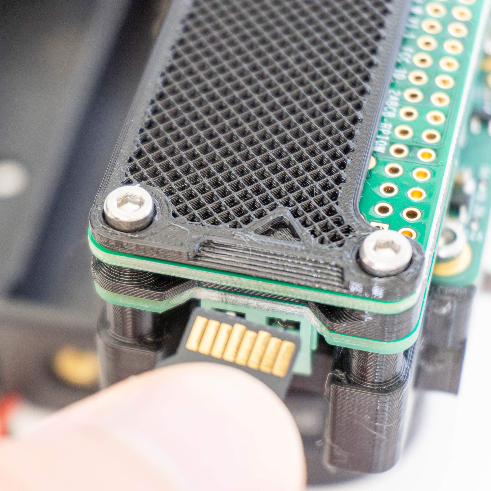
Grab the SD-card and push it into the SD-card connector of the Pi Zero. Contacts need to be facing toward the Raspberry Pi Zero (as shown in the image above).
Last step before doing the first boot: Backfocus adjustment.
Some C/CS-lenses are fixed focus lenses, some offer an additional focus adjustment mechanism in the lens itself. The official 6mm wide-angle lens is one that offers this. However, in both cases the backfocus needs to be adjusted (the correct spacing of lens to sensor). If you’ve got a fixed focus lens you would usually set your backfocus so that infinity is in focus and you’re done.
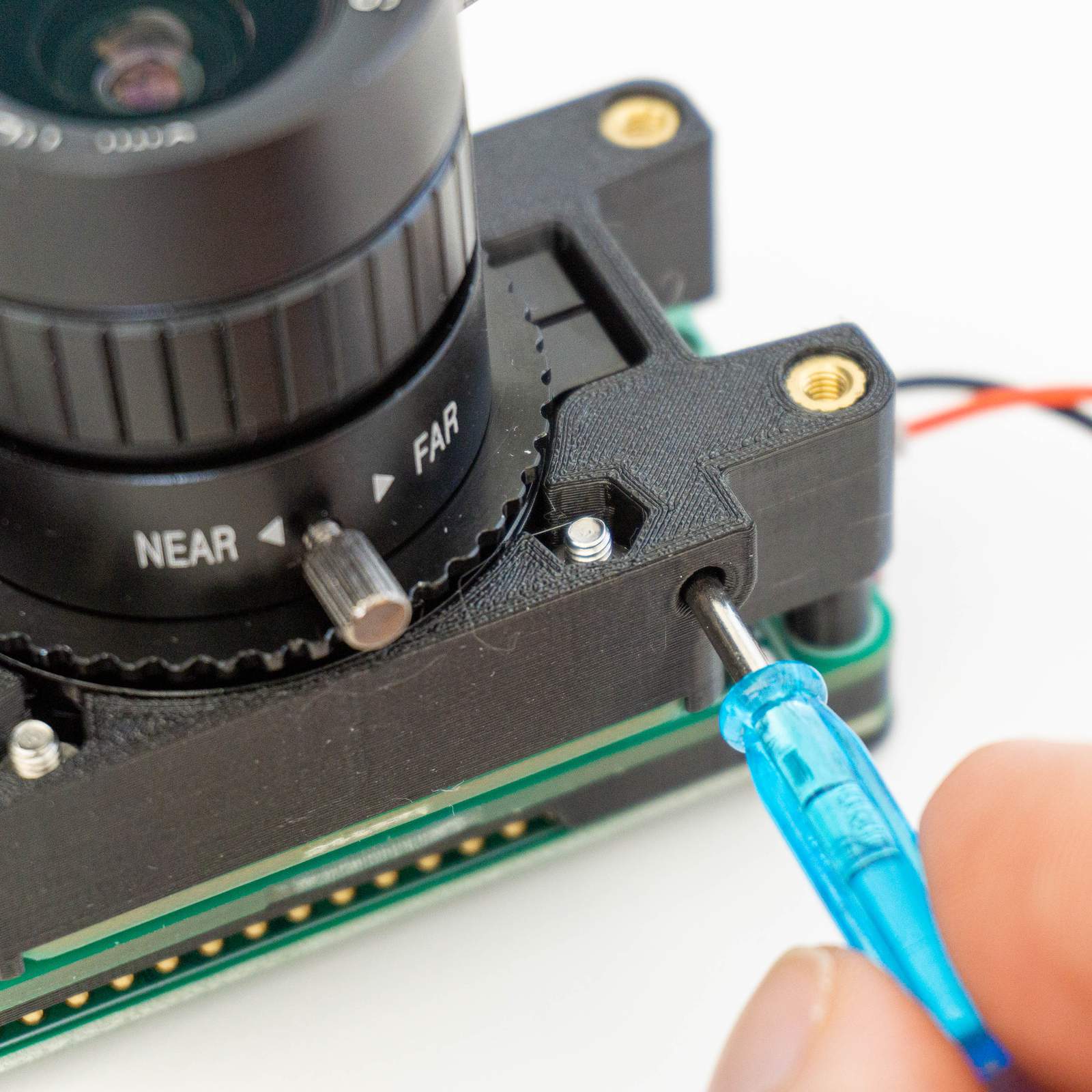
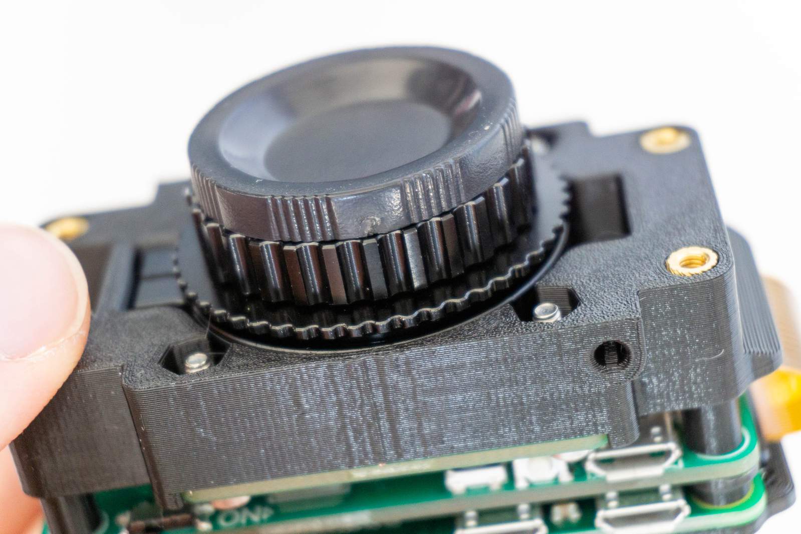
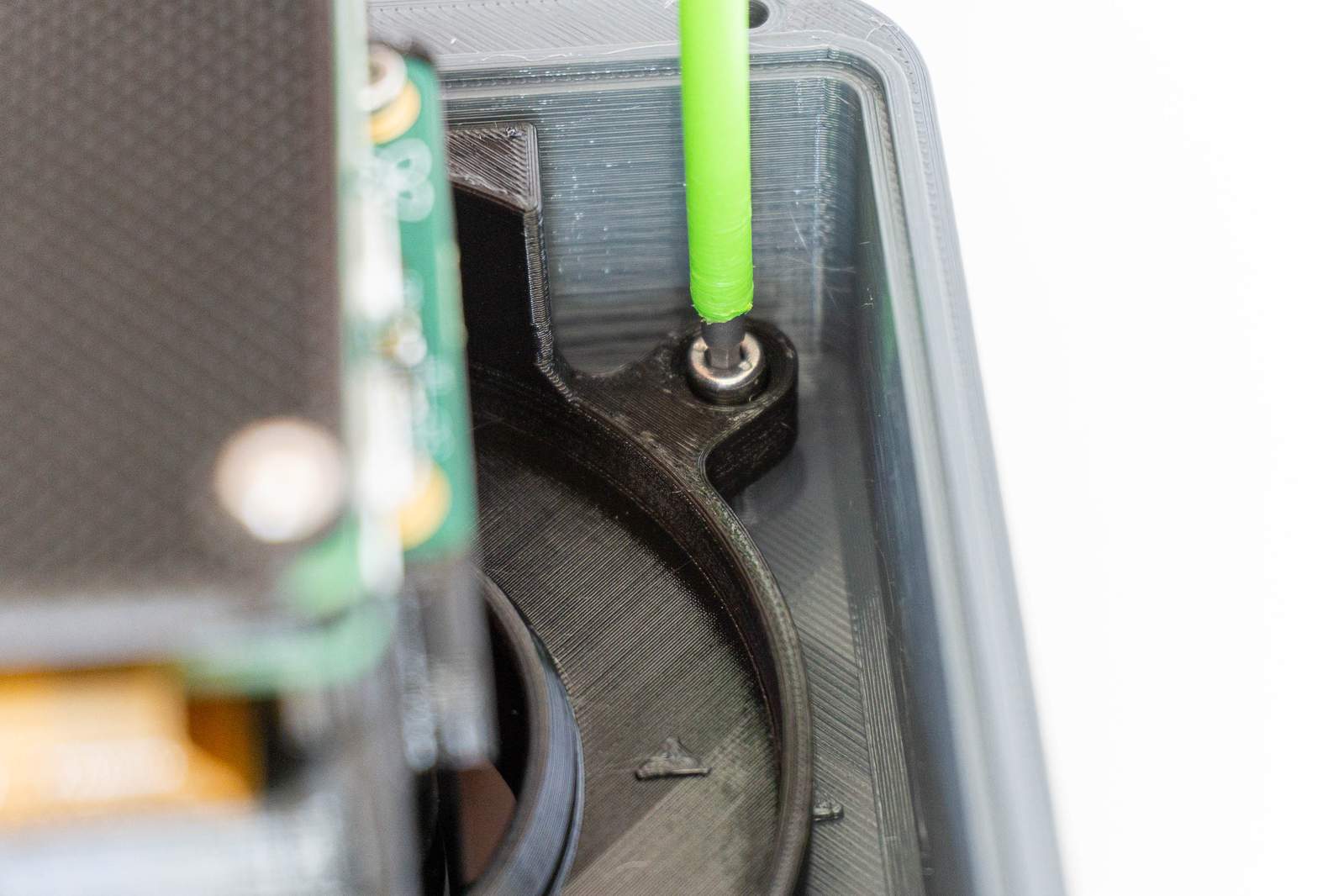
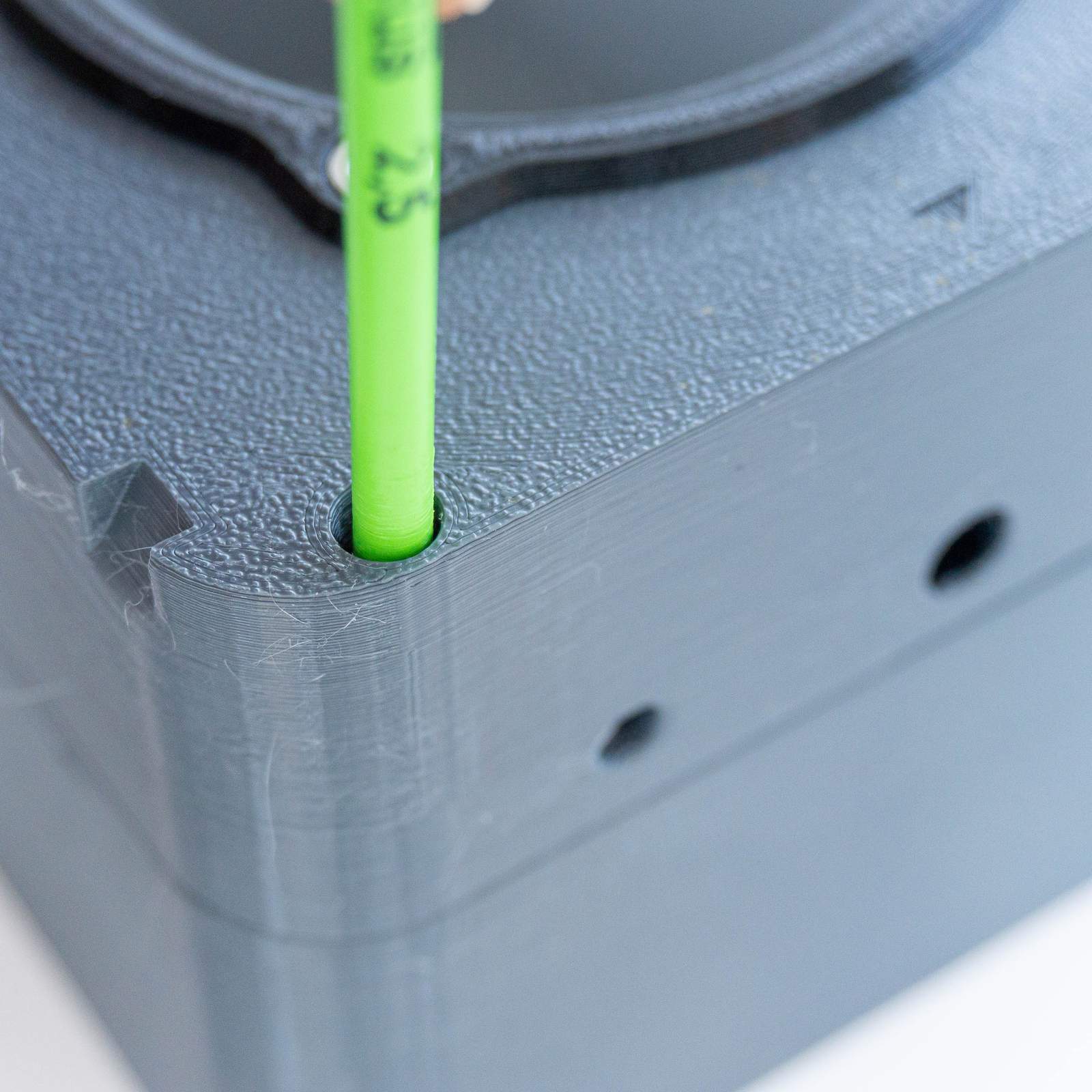
In order to do that, we need to use the blue screwdriver that came with the Camera Module and loosen the backfocus adjustment screw. Push the screwdriver through the hole (as seen in the image) and rotate it slightly till you feel that the screwdriver is actually engaging the screw (is that the correct phrase in english? whatever, you know what I mean…). Loosen the screw a bit and then you are able to rotate the ring the lens sits on (it’s lubricated in a way that increases resistance so don’t be surprised if it takes a bit of force).
Put the fully charged batteries in the battery holder (mind the orientation!).
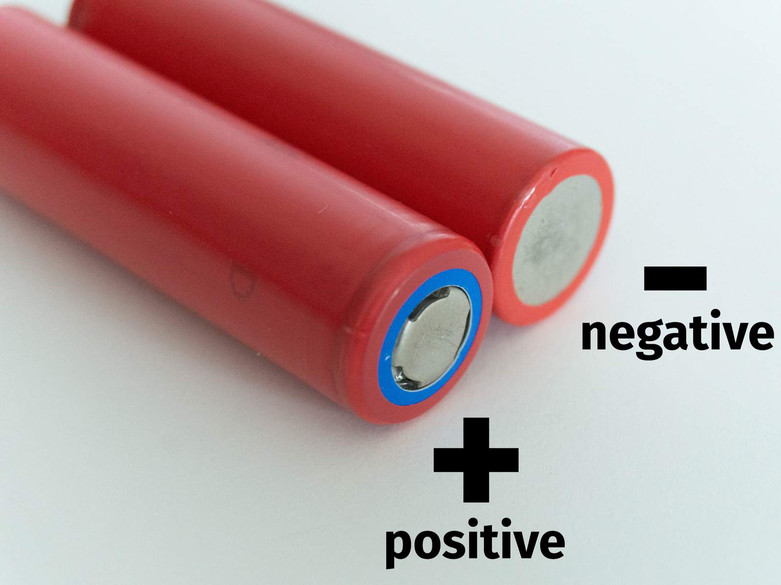
Note: 18650 batteries usually have a flat positive pole. So unlike smaller batteries the plus side is less pronounced. You can always differentiate the sides by knowing that the negative side is completely flat while the positive side looks different. The negative side needs to be placed on the spring in the holder. Molded into the plastic of the holder you will find an additional note on how to orient them.
If the batteries are inserted push the on/off-switch to ON (marked with (a) in the picture below, should usually be already set to on because I am testing each board before packaging).
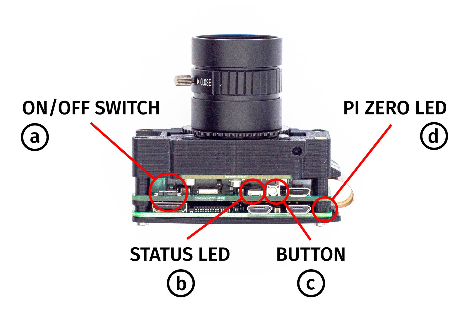
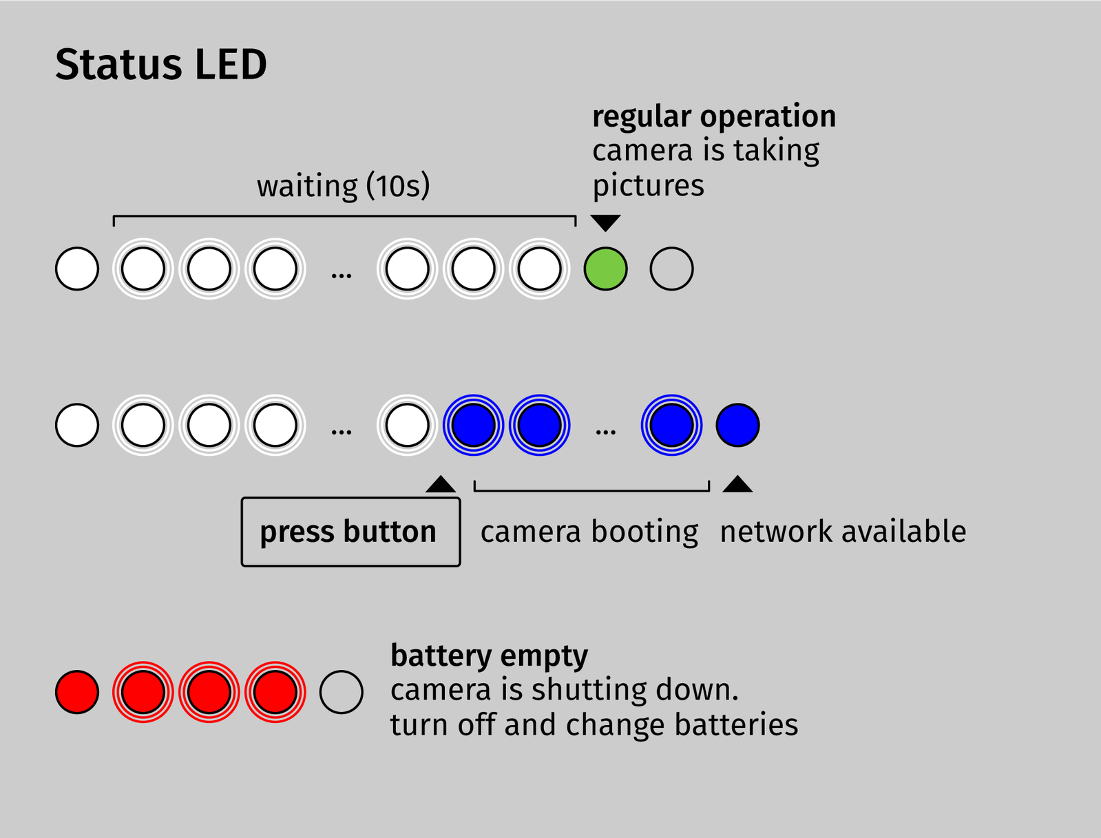
The status LED (b) on the CompressorCamera board will now start and blink white for 10s. During this time the camera is waiting for user input.
If you push the button (c) while the LED is blinking white, the status LED (b) will start to blink blue and the camera starts in maintenance mode. Maintenance mode means that the camera creates a Wifi network and will wait for further input. If the button is not pressed, the LED (b) will be green for 1 second, the camera starts normally and begins capturing (the Pi Zero LED (d) will begin to flicker).
(if your camera did already start in regular mode and is now happily taking pictures, move the on/off-switch to the right to power of the camera, move it to the left to power it on again and then press the button to start in maintenance mode)
After 30 seconds the camera is fully booted and will provide a Wifi-hotspot. You can connect with your computer to the CompressorCamera Wifi-network now. When the camera is starting for the very first time, this may take slightly longer. As soon as the status LED is stopping to blink, the wifi network is available. The default password is ccampassword. Open the compressor.camera website and click on focus in the sidebar (this will only work when you are connected to the CompressorCamera network). What you will see now is a 100% crop of the center of the camera image. Click on the image to let the camera take a new picture (this may take a few seconds). Based on this crop you can rotate the ring that holds the lens to adjust the backfocus of the lens. The image will be extremly blurry in the start since the Camera Module is shipped with the backfocus ring fully screwed in. You may need to rotate the ring for 1 or 2 full revolutions till the camera output resembles an actual image. Refresh by clicking on the image, rotate the ring a bit, refresh again, …
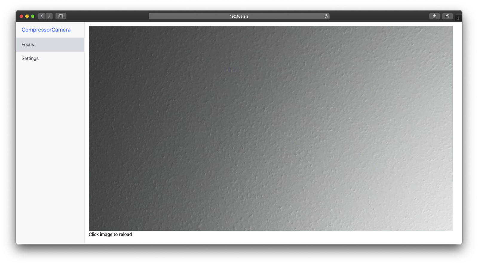
If you point your camera to your ceiling and you got a very classic german wallpaper texture, then it would look like the image above.
If you did find the best focus position and your camera output is nice and sharp, fasten the screw with the blue screwdriver. The lens is now secured and focussed and you are not able to rotate the backfocus ring any further. You can switch the camera off with the power switch on the board.
Finish the enclosure
Grab the printed spacers and the 35mm long M2.5 screws.
Place the four screws in the holes and slip the spacers over the screws. The rounded side should be facing inwards.
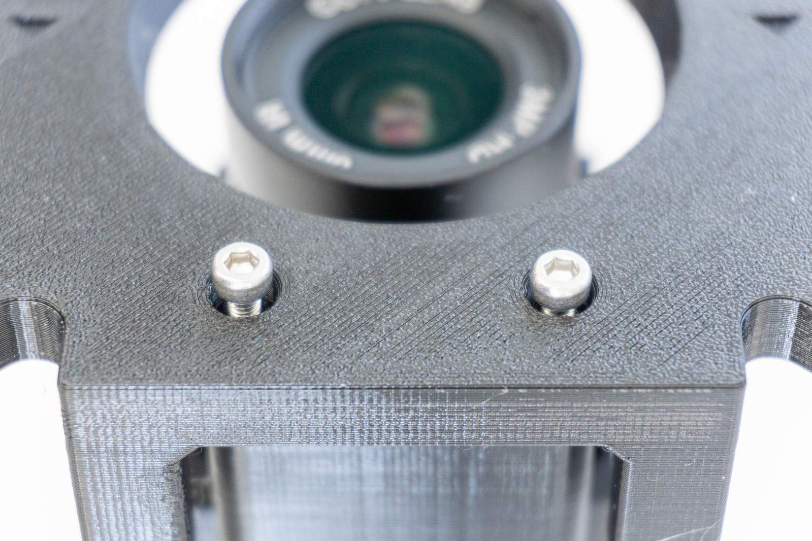
Screw the camera assembly to the spacers and join insert and camera.
And that’s how the insert with the camera electronics should look like.
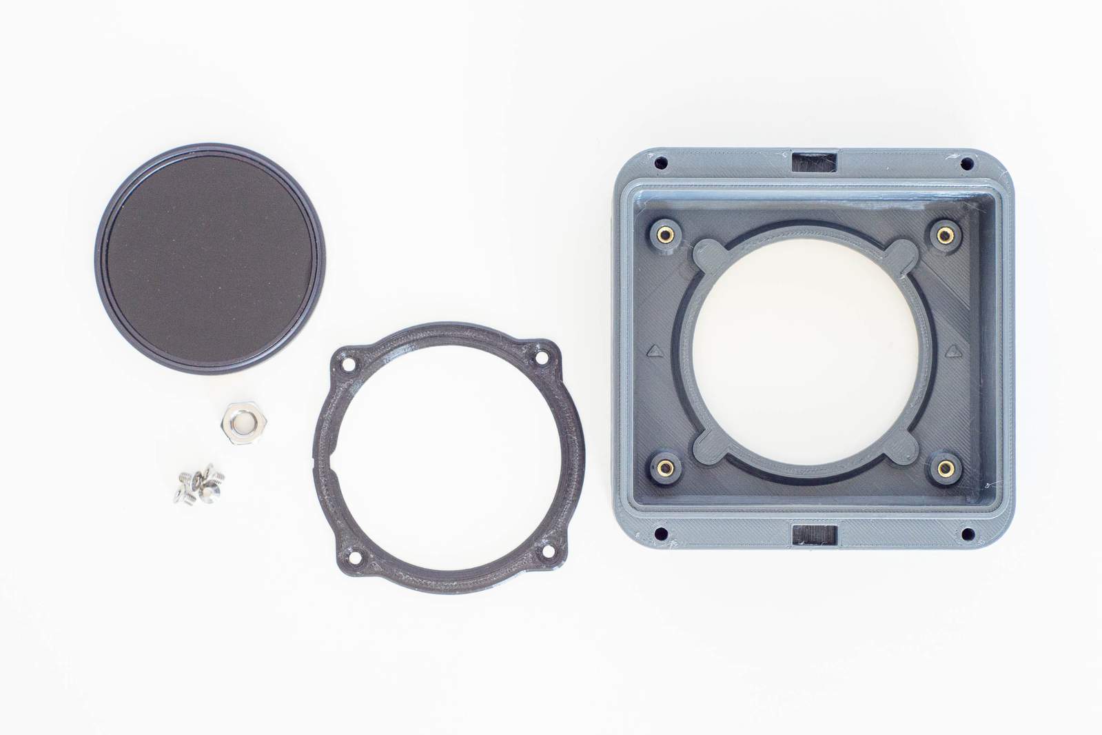
Now we need to assemble the top element of the enclosure, fastening the filter and its printed front element.
Now get the neutral density filter out of the box and place it cautiously in the top part of the enclosure.
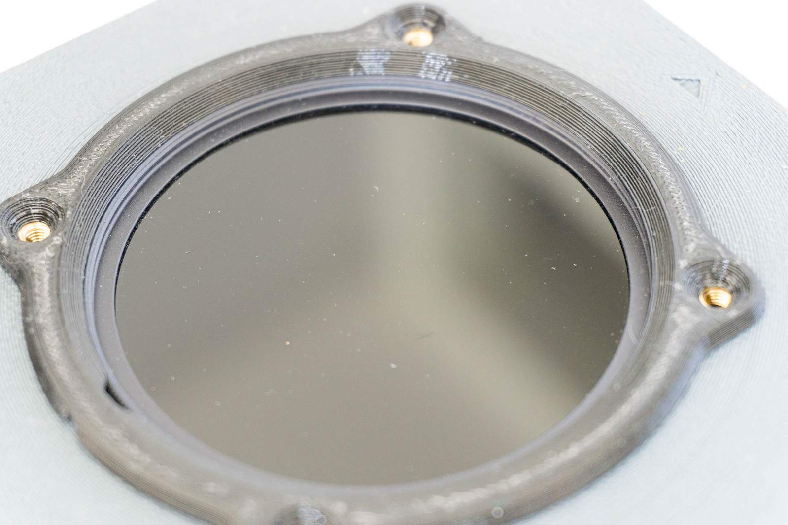
Place the filter front element on top of the filter. The gap in the plastic part should face downwards when placing the enclosure outdoors so rain hitting the filter can drain.
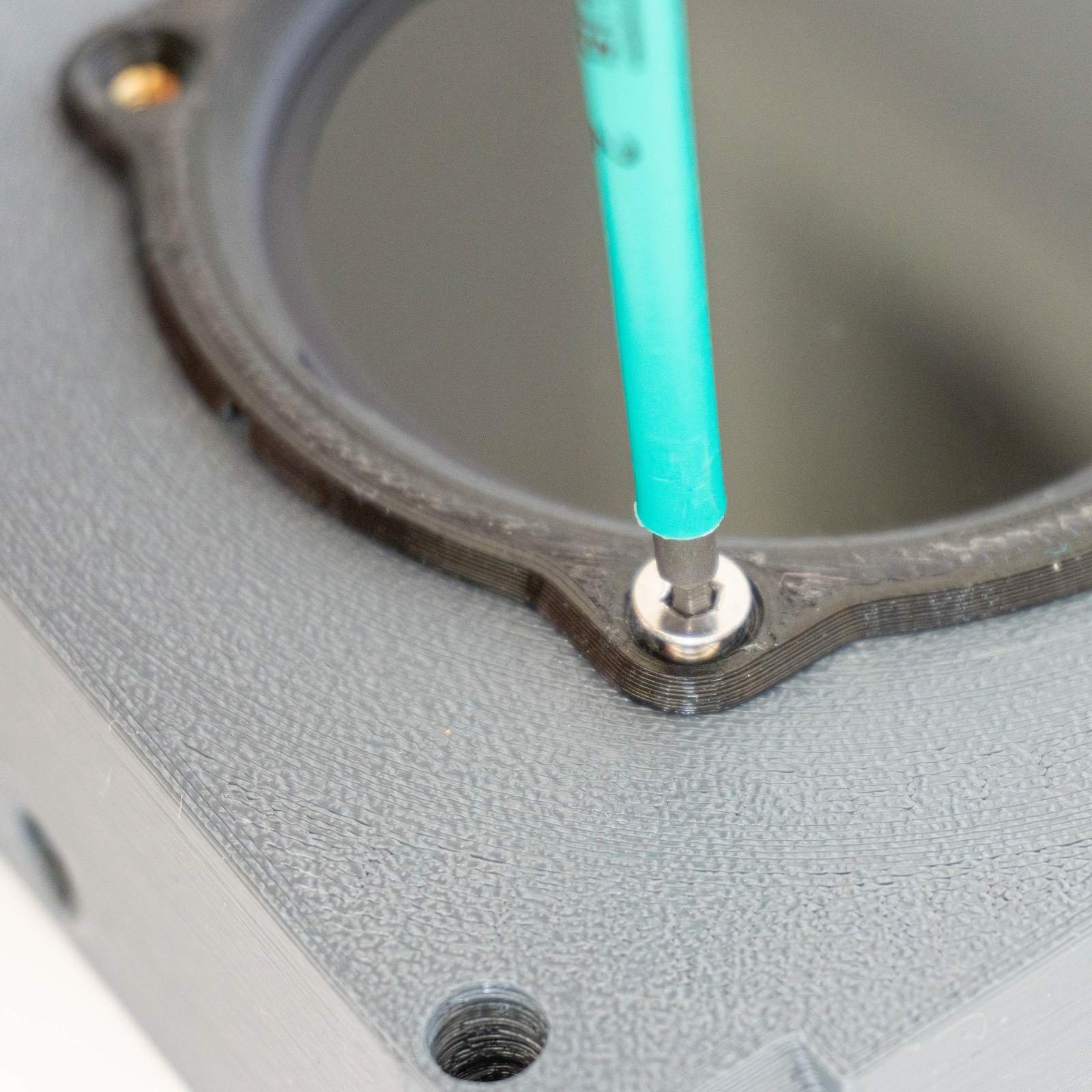
Fasten the filter front element with the four tiniest screws found in the package.
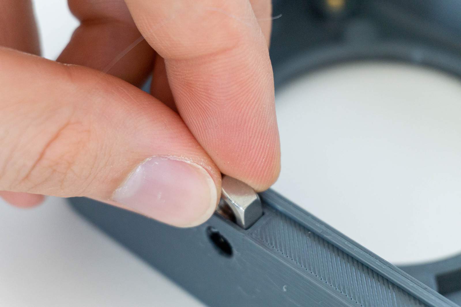
Place the nut either in the upper or lower tripod nut cavity. Since the enclosure is (almost) symmetrical, it doesn’t make a difference which one you are using.
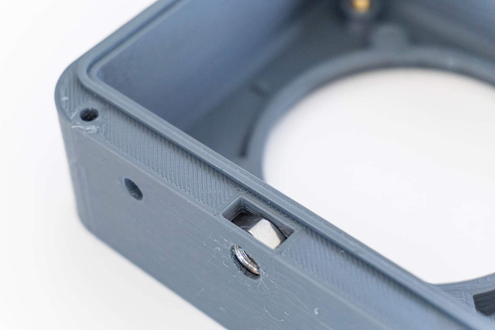
The tripod nut should be sitting flush as shown in the image above.
Last step: screw the insert with the camera into the upper enclosure half and close the enclosure.
Screw in the four 6mm screws to connect the insert to the top part of the enclosure.
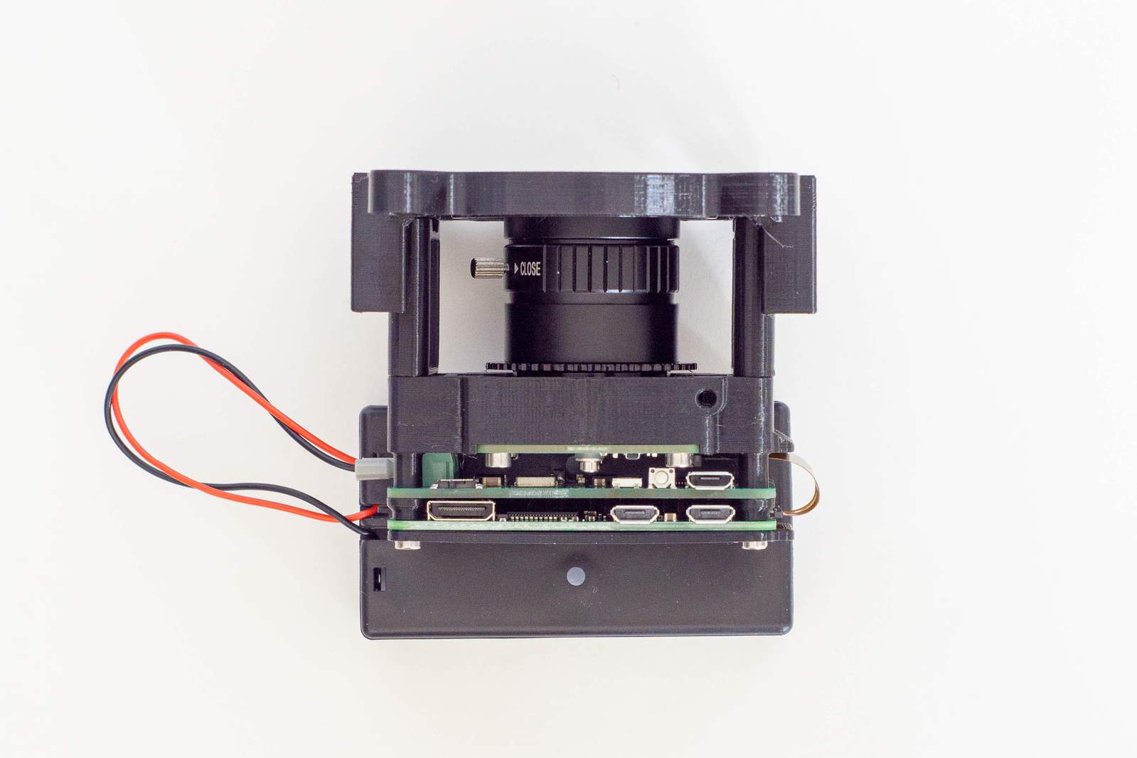
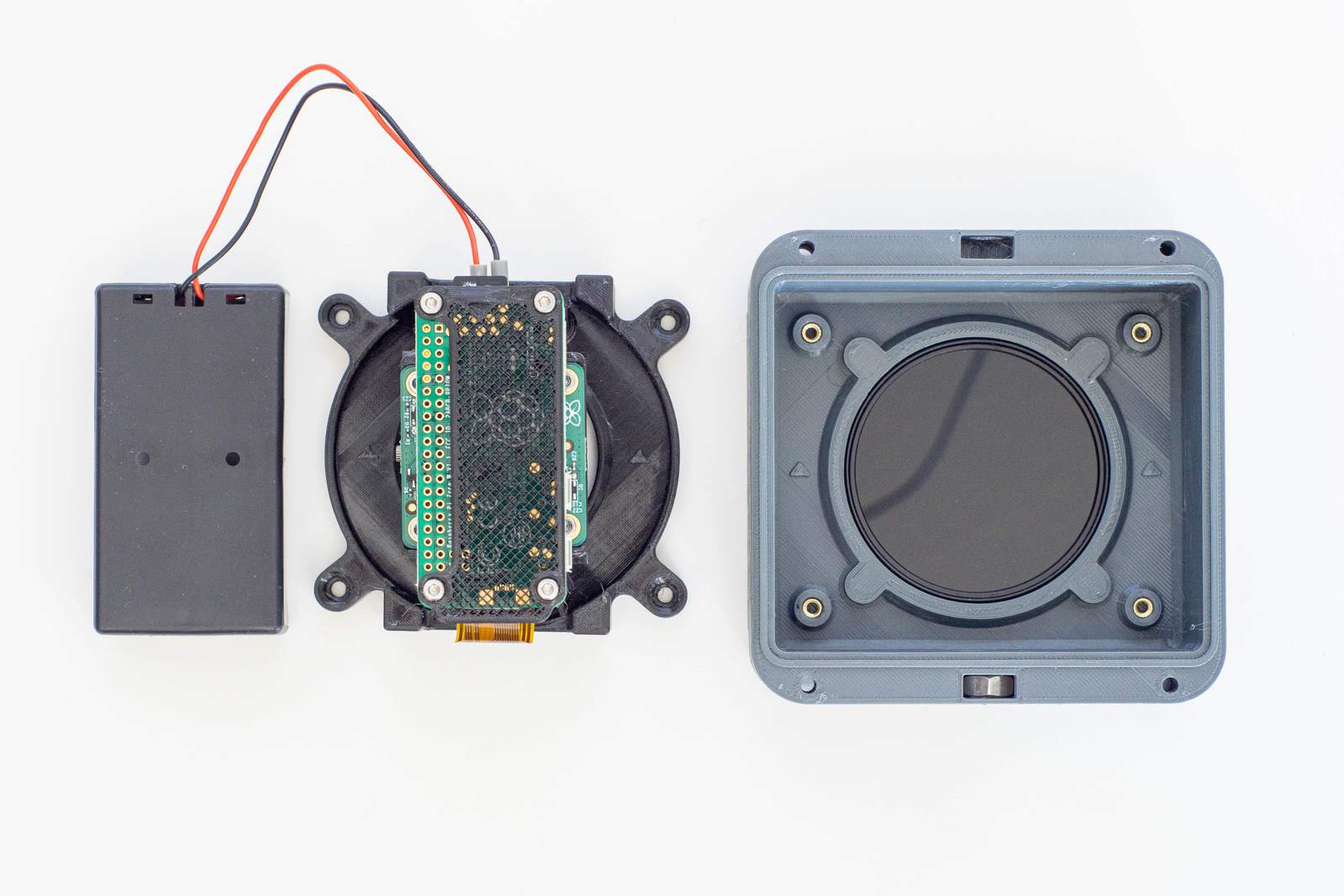
When placing the insert with the camera and the battery holder in the enclosure, make sure that the batteries in the holder are facing outwards. If the battery holder is placed like in the photo above, it is easier to stash the cables.
Use the last four screws (these are either 50mm long or 60mm long, depending on the type of enclosure you’ve got) to close the enclosure. Only the last 4mm of the screw are engaging with the thread in the lower part of the enclosure. So place every screw in the hole and press the upper part of the enclosure a bit down. Then fasten one screw a bit, move on to the next one diagonally and fasten that a bit, too. Then you can fasten all four screws completely till both halves are flush. The screws need to compress the seal in between but if upper and lower half touch, the seal is tight.
Take images
Now take the camera to it’s location, fasten it on the tripod or fix it to a pole with zipties and you are done.
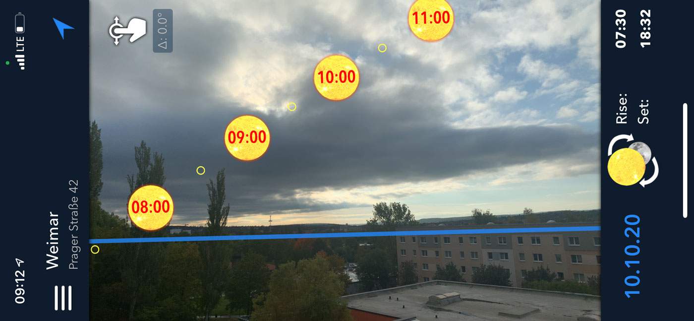
When scouting locations it is advisable to get an understanding where the sun will be visible at which time. There are a few apps that show an Augmented Reality-like overview on your smartphone, such as Photographers Ephemeris or Lumos for iOS. Lumos is what I use and recommend, since it’s simple and does it’s job exceptionally well.
Copy the data
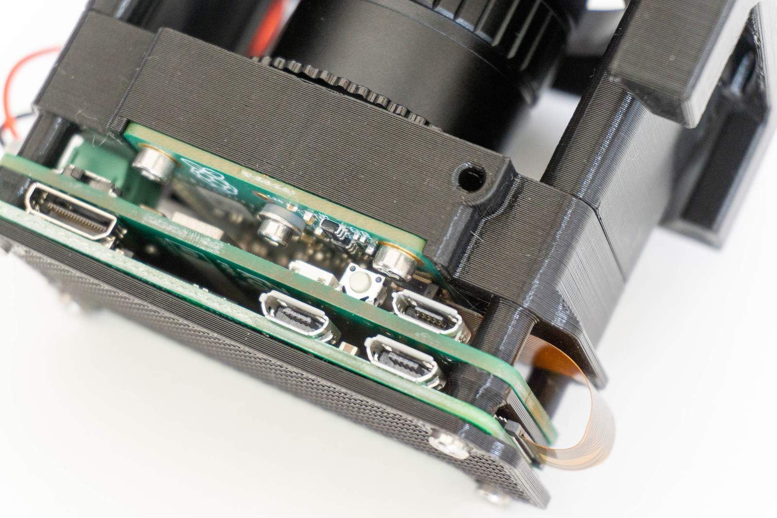
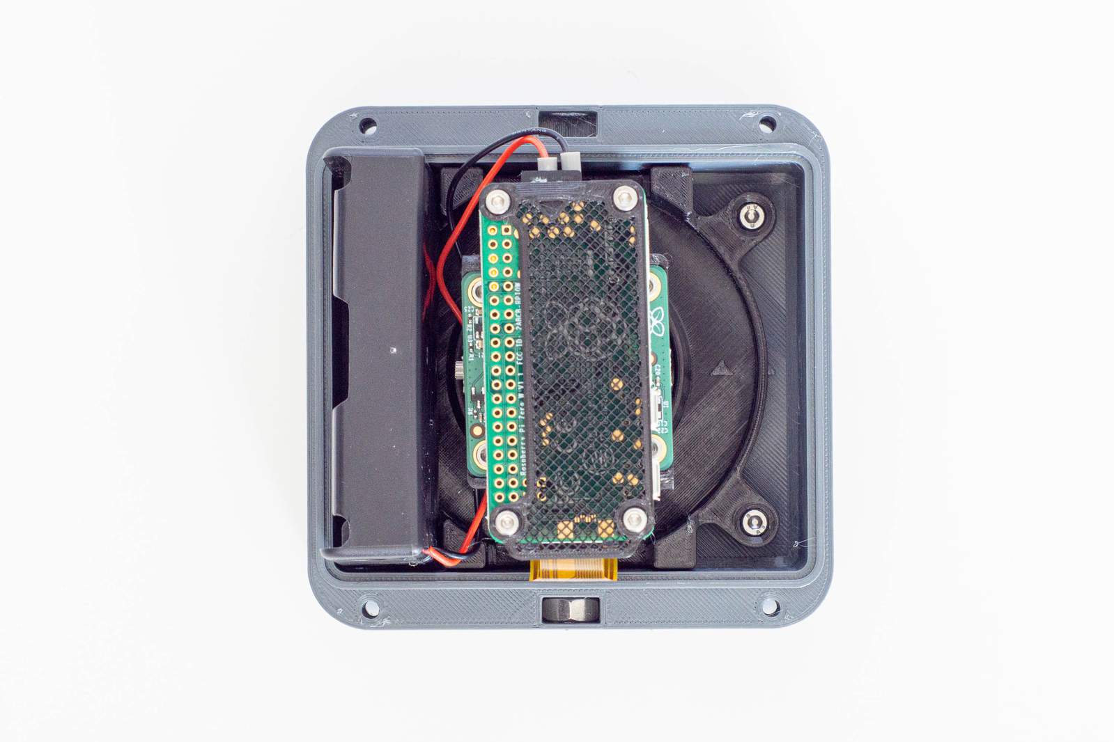
After a day or two, grab your camera again and open the enclosure. Make sure that the LED of the Pi Zero (see image) is not on before moving the switch to off and remove the SD-card.
If you use Windows or MacOS, the SD-card will show two partitions. One rather small one which you can ignore and a second one called CCSTORAGE. If you are using Linux, you will see a third ext4-formatted partition which contains the operating system, but you can ignore that.
On the CCSTORAGE partition you will find four folders and a text file that contains the log-output of the camera. Copy the four folders to your computer and delete them from the SD-card to free up space for next time. Have a look at the captures_regular folder and see if you may need to delete the first or last few images (because the camera was running before you placed it on location).
Postprocess
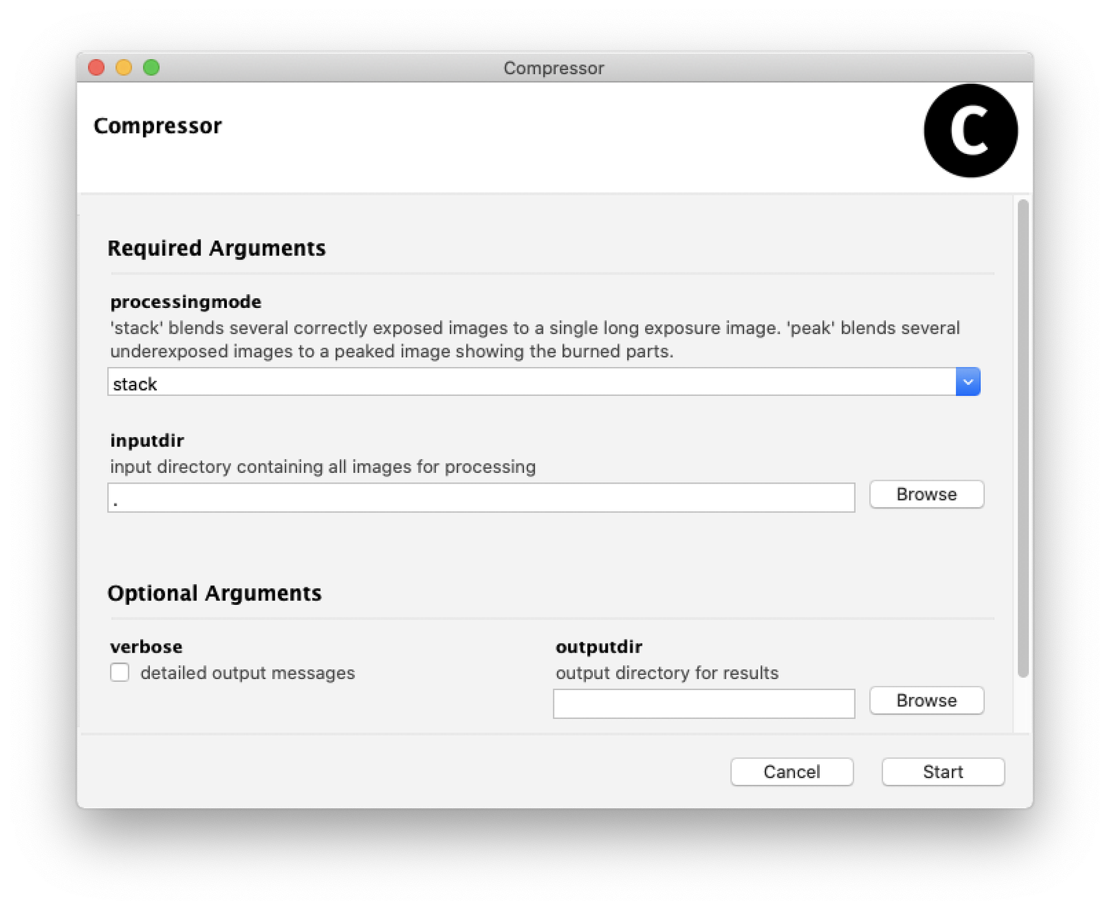
Download the compressor software for Windows 10 or MacOS. You will find the latest release here. Start the application (may take a few seconds) and select the first folder (capture_regular) as input. Set the processing mode to stack and hit start. The compressor software will now combine all correctly exposed images and compute (based on the metadata) a long exposure image. If you did not select a specific output directory, the output will be stored in captures_regular_stacked.
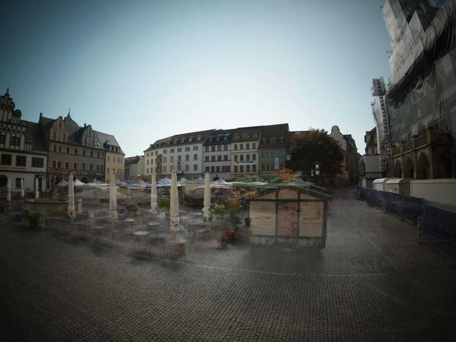
This will result in a correctly exposed long exposure image, as above.
Repeat this with the other three directories but set the processing mode to peak. This may take a few minutes depending on the number of captures.
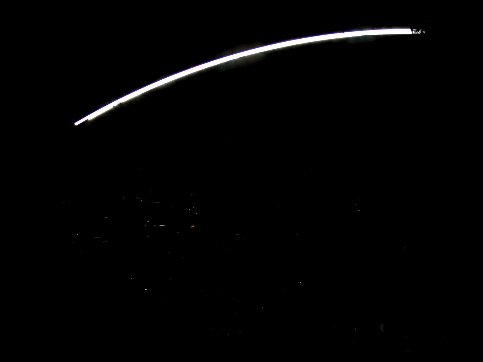
The peaking images will only contain the extremly overexposed parts of the image, as above.
Merge the resulting images in your preferred software such as Photoshop or Gimp. What usually works well is to use the long exposure image as the base layer and overlay the peaked images in either Lighten or Screen blend mode.
Additional info:
Never flip the batteries!
I assume it is not necessary to state this, but I will do it nevertheless: never place the batteries in the holder reversed! Never confuse the battery holder cables! Never use a conductive screwdriver to remove the batteries from the holder! Reverse polarity will destroy the electronics instantly. You are using 18650 Lithium-Ion cells and short-circuiting these batteries will release enough energy to get glowing red metal in a matter of seconds. Cells will be impossible to touch and may explode. Do not discharge the batteries below 3V per battery (the CompressorCamera board will shutdown and cease to work at 3.1V in order to protect the batteries before they reach deep-discharge levels).
Do not leave the batteries in the camera over an extended amount of time
Even when the switch is set to off the circuit will draw an incredibly tiny but constant amount of power. Remove the batteries when not using the camera for several weeks and recharge them before the next usage.